Accuracy (combined with axf remote flowtube), Caution – Yokogawa AXFA14G/C User Manual
Page 16
IM 01E20C02-01E
11. OUTLINE
Accuracy (Combined with AXF Remote Flowtube)
Pulse Output:
PFA/Ceramics Lining:
Size mm
(in.)
V
Ͻ 0.3 (1)
Ϯ1.0 mm/s
Ϯ0.5 mm/s
Ϯ0.5 mm/s
0.3
Ϲ V Ϲ 10
(1) (33)
V Ͻ 0.15 (0.5)
V Ͻ 0.15 (0.5)
0.15
Ϲ V Ϲ 10
(0.5) (33)
0.15
Ϲ V Ϲ 10
(0.5) (33)
V Ͻ0.15 (0.5)
0.15
Ϲ V Ͻ1
(0.5) (3.3)
Ϯ0.35% of
Rate
Ϯ0.5 mm/s
Ϯ0.35% of
Rate
Ϯ0.35% of
Rate
2.5 (0.1)
to
15 (0.5)
250 (10)
to
400 (16)
25 (1.0)
to
200 (8.0)
—
—
Flow Velocity
V m/s (ft/s)
Flow Velocity
V m/s (ft/s)
Standard
Accuracy
(Calibration
code B)
High grade
Accuracy
(Calibration
code C)
Ϯ0.18% of Rate
Ϯ0.2mm/s
1
Ϲ V Ϲ10
(3.3) (33)
Ϯ0.2% of Rate
T01.EPS
Enhanced dual frequency excitation (Option code HF2):
Standard accuracy
Ϯ 1 mm/ s
Size 2.5 mm (0.1 in.) to 15 mm (0.5 in.)
1.2
1.0
0.8
0.6
0.4
0.35
0.2
0
0
1
2
6
8
10
V[m/s]
High grade Accuracy
High grade Accuracy
Standard Accuracy
F01.EPS
Pulse
Output
Accuracy
% of Rate
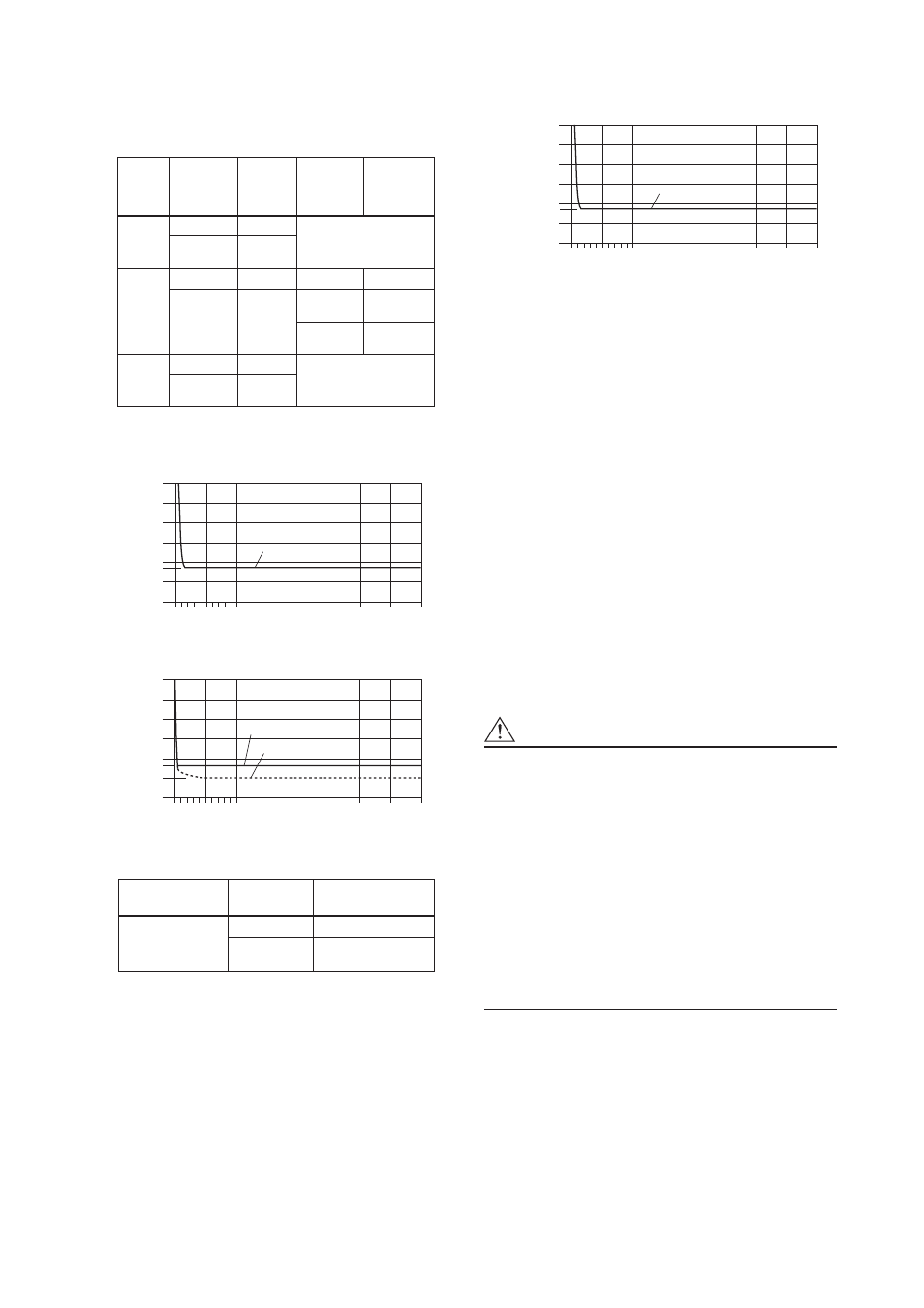
Size 25 mm (1.0 in.) to 400 mm (16 in.)
1.2
1.0
0.8
0.6
0.4
0.35
0.2
0
0
1
2
6
8
10
V[m/s]
F02.EPS
Pulse
Output
Accuracy
% of Rate
Standard Accuracy
High grade Accuracy
Polyurethane Rubber/Natural Soft Rubber/EPDM
Rubber Lining
Size mm (in.)
V
Ͻ 0.3 (1.0)
Ϯ1.0 mm/s
0.3
Ϲ V Ϲ 10
(1.0) (33)
Ϯ0.35% of Rate
25 (1.0) to 400 (16)
Flow Velocity
V m/s (ft/s)
Standard Accuracy
(Calibration code B)
T02.EPS
Enhanced dual frequency excitation (Optional code HF2):
Standard accuracy
Ϯ 1 mm/ s
Size 25 mm (1.0 in.) to 400 mm (16 in.)
1.2
1.0
0.8
0.6
0.4
0.35
0.2
0
0
1
2
6
8
10
V[m/s]
High grade Accuracy
High grade Accuracy
Standard Accuracy
F01.EPS
Pulse
Output
Accuracy
% of Rate
Current Output “
᭛”: Pulse output accuracy plus Ϯ0.05% of Span
Repeatability:
Ϯ0.1% of Rate (V м 1 m/s (3.3 ft/s))
Ϯ0.05% of Rate Ϯ0.5 mm/s (V < 1 m/s (3.3 ft/s))
Maximum Power Consumption:
Combined with AXF Remote Flowtube: 12 W
Insulation Resistance(*1) :
Between power supply terminals and ground
terminal: 100M
Ω at 500V DC
Between power supply terminals and input/output/
excitation current terminals : 100M
Ω at 500V DC
Between ground terminal and input/output/excitation
current terminals: 20M
Ω at 100V DC
Between input/output/excitation current terminals
:20M
Ω at 100V DC
Withstand Voltage(*1) :
Between power supply terminals and groundterminal:
1400V AC for 2 seconds
Between power supply terminals and input/output termi-
nals: 1400V AC for 2 seconds
Between excitation current terminal and ground terminal:
160V AC for 2 seconds
Between excitation current terminal and input /output
terminals: 350V AC for 2 seconds
CAUTION
*1: When performing the Insulation Resistance Test or the
Withstand Voltage Test, please obey the following
caution.
• Following the relevant test, wait for more than 10
seconds after the power supply has been turned off
before removing the cover.
• Remove all wires from terminals before testing.
• When the power terminal has a lighting protector
(optional code A), remove the short bar at the ground
terminal.
• After testing, be sure to discharge by using a resis-
tance and return all wires and the short bar to its
correct position.
• Screws must be tightened to a torque of 1.18 N-m or more.
• After closing the cover, the power supply can be restored.
11-3