2 terminal configuration, 3 precautions for wiring of power supply cables – Yokogawa AXFA14G/C User Manual
Page 11
IM 01E20C02-01E
4-5
4. WIRING
4.4.2
Terminal Configuration
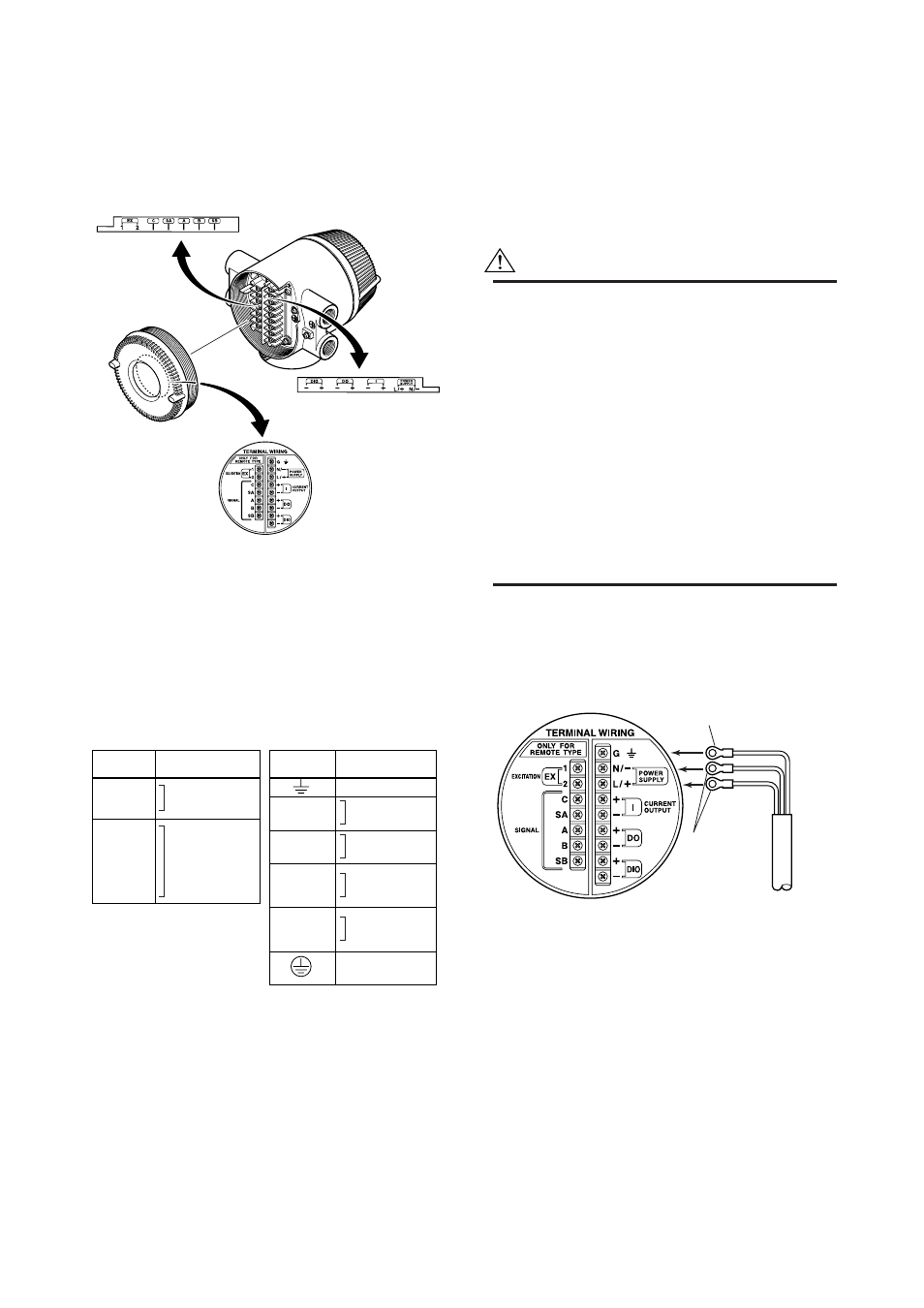
When the cover is removed, the connection terminals
will be visible. The terminal configuration labels are
attached in the locations shown in Figure 4.4.2.
F0409.EPS
Figure 4.4.2
Terminal Layout Labels Position
The description of the terminal symbols is shown in
Table 4.1.1.
For F
OUNDATION
Fieldbus protocol, please refer to IM
01E20F02-01E.
For PROFIBUS PA protocol, please refer to IM
01E20F12-01E.
Table 4.1.1 Terminal Symbols
T0401.EPS
Flow singal
input
Excitation current
output
Power supply
Current output
4 to 20mA DC
Pulse output/
Alarm output/
Status output
Alarm output/
Status output/
Status input
Functional
grounding
Terminal
Symbols
Description
EX1
EX2
C
SA
A
B
SB
Terminal
Symbols
Description
N/–
L/+
I+
I–
DO+
DO–
DIO+
DIO–
Protective grounding
(Outside of the terminal)
4.4.3
Precautions for Wiring of Power
Supply Cables
When connecting to the power supply, observe the
points below. Failure to comply with these warnings
may result in an electric shock or damage to the
instrument.
WARNING
• Ensure that the power supply is OFF in order to
prevent electric shocks.
• Ensure the protective grounding terminal is
grounded before turning the power on.
• Use insulating sleeve crimp terminals (for 4-mm
screws) for the power supply wiring and protec-
tive grounding wiring.
• Install an external switch or circuit breaker as a
means to turn the powe off (capacitance; 15A,
conforming to IEC60947-1 and IEC60947-3).
Locate this switch either near the instrument or
in other places facilitating easy operation. Affix
a “Power Off Equipment” label to this external
switch or circuit breaker.
Wiring Procedure
1. Turn the instrument's power off.
2. Wire the power supply cable and the functional
grounding cable to the power supply terminals.
F0410.EPS
Functional grounding cable
Power supply
cable
Figure 4.4.3
Electric Cable Wiring