8 installing the cover – Yokogawa AXFA14G/C User Manual
Page 15
IM 01E20C02-01E
4-9
4. WIRING
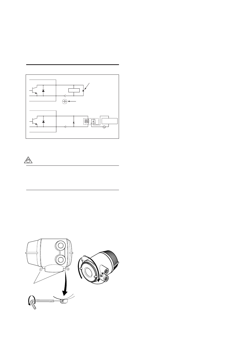
This output cannot switch an AC load. To switch
an AC load, an intermediate relay must be
inserted as shown in Figure 4.4.11.
*The alarm output operates from open (normal)
to closed (alarm occurrence) in the default value
(as setup upon plant shipment). Changes can
be made via the parameter settings.
F0419.EPS
Load
Protective diode
External power supply
30V DC, 0.2A. max
AXFA14
AXFA14
This connection is not possible.
DO+ (or DIO+)
DO- (or DIO-)
DO+ (or DIO+)
DO- (or DIO-)
Electromagnetic
valve
AC power supply
Relay
Figure 4.4.11 Status Output/Alarm Output Connection
NOTE
For status and alarm outputs from the DO or
DIO terminals, parameters must be set. Refer to
“Chapter 6: Parameter Description” in this
manual.
4.4.8
Installing the Cover
Install the cover to the flowmeter by turning it in the
direction of the arrow as shown below. Tighten cover
locking screw 2 counterclockwise using a hexagonal
wrench (nominal size 3 mm) to lock the cover.
F0420.EPS
Cover locking
screws
Figure 4.4.12 Installing the Terminal Box Cover