Yokogawa AXFA14G/C User Manual
Page 14
IM 01E20C02-01E
4-8
4. WIRING
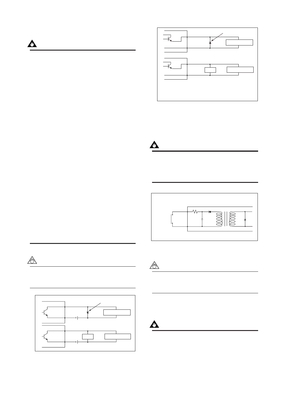
᭹ Pulse Output
IMPORTANT
• As this is a transistor contact (insulated type),
give attention to proper voltage and polarity
when wiring.
• Do not apply a voltage larger than 30V DC or a
current larger than 0.2A in order to prevent
damage to the instrument.
• When input filter constant of the electronic
counter is large in relation to the pulse width,
the signal will decrease and the count will not
be accurate.
• If the input impedance of the electronic counter
is large, an induction noise from the power
supply may result in inaccurate counts. Use a
shield cable or sufficiently reduce the input
impedance of the electronic counter within the
electromagnetic flowmeter pulse output specifi-
cation range.
• The active pulse output (Optional code EM)
cannot be used in conjunction with the standard
pulse output.
• When the active pulse output (Optional code
EM) is selected, do not be short-circuit between
the DO+ and DO– terminals to avoid damaging
the instrument.
• When the active pulse output (Optional code
EM) is selected, the range of pulse rate must
be set to 2 pps maximum.
• To avoid communication (BRAIN/ HART)
failure, it is recommended to use the shield
cable.
NOTE
For pulse output from the DO terminals, param-
eters must be set. Refer to “Chapter 6: Param-
eter Description” in this manual.
F0416.EPS
Mechanical Counter
Electronic Counter
Load
Protective diode
30V DC, 0.2A. max
PULSE OUT
PULSE OUT
AXFA14
AXFA14
DO+
DO-
DO+
DO-
Figure 4.4.8
Pulse Output Connection
F0417.EPS
Protective diode
PULSE OUT
AXFA14
AXFA14
DO+
DO-
DO+
DO-
Output voltage: 24 V DC
Ϯ20%
Current: 150 mA or less
Pulse rate: 0.0001 to 2 pps
Pulse width: 20, 33, 50, 100 ms
Mechanical Counter
Electronic Counter
Load
PULSE OUT
Figure 4.4.9
Active Pulse Output Connection (Optional
code EM)
᭹ Status Input
IMPORTANT
Status inputs are designed for use with no-
voltage (dry) contacts. Be careful not to connect
the status to any signal source carrying voltage.
Applying voltage may damage the input circuit.
AXFA14
DIO+
DIO-
F0418.EPS
No-voltage status input
Closed: Less than 200
Ω
Open:
More than 100 k
Ω
Figure 4.4.10 Status Input Connection
NOTE
For status input to the DIO terminals, parameters
must be set. Refer to “Chapter 6: Parameter
Description” in this manual.
᭹ Status Output / Alarm Output
IMPORTANT
Since this is an isolated transistor output, be
careful of voltage and polarity when wiring. Do
not apply a voltage larger than 30V DC or a
current larger than 0.2A in order to prevent
damage to the instrument.