7 connecting to external instru- ments – Yokogawa AXFA14G/C User Manual
Page 13
IM 01E20C02-01E
4-7
4. WIRING
4.4.6
Wiring the Remote Flowtube
with the AXFA14 Converter
WARNING
Before wiring, be sure that the power supply for
AXFA14 converter has been turned off to
prevent an electrical shock.
(1) Connection with the Remote Flowtube
(General-Purpose Use, Submersible Type,
Sanitary Type, Size 2.5 to 400 mm (0.1 to
16 in.))
Connect wiring as shown in the figure below.
AXFC dedicated
signal cable
EX2
EX1
A
B
C
Excitation cable
EX1
EX2
C
SA
A
B
SB
F0413.EPS
Converter
Remote
flowtube
SA
A
B
SB
C
EX1
EX2
Taping*
A
B
Taping*
C
EX1
EX2
* Individually tape and insulate the
shields corresponding to SA and
SB on the remote flowtube side.
AXFA14 Converter
Remote flowtube
Figure 4.4.5
Wiring Diagram
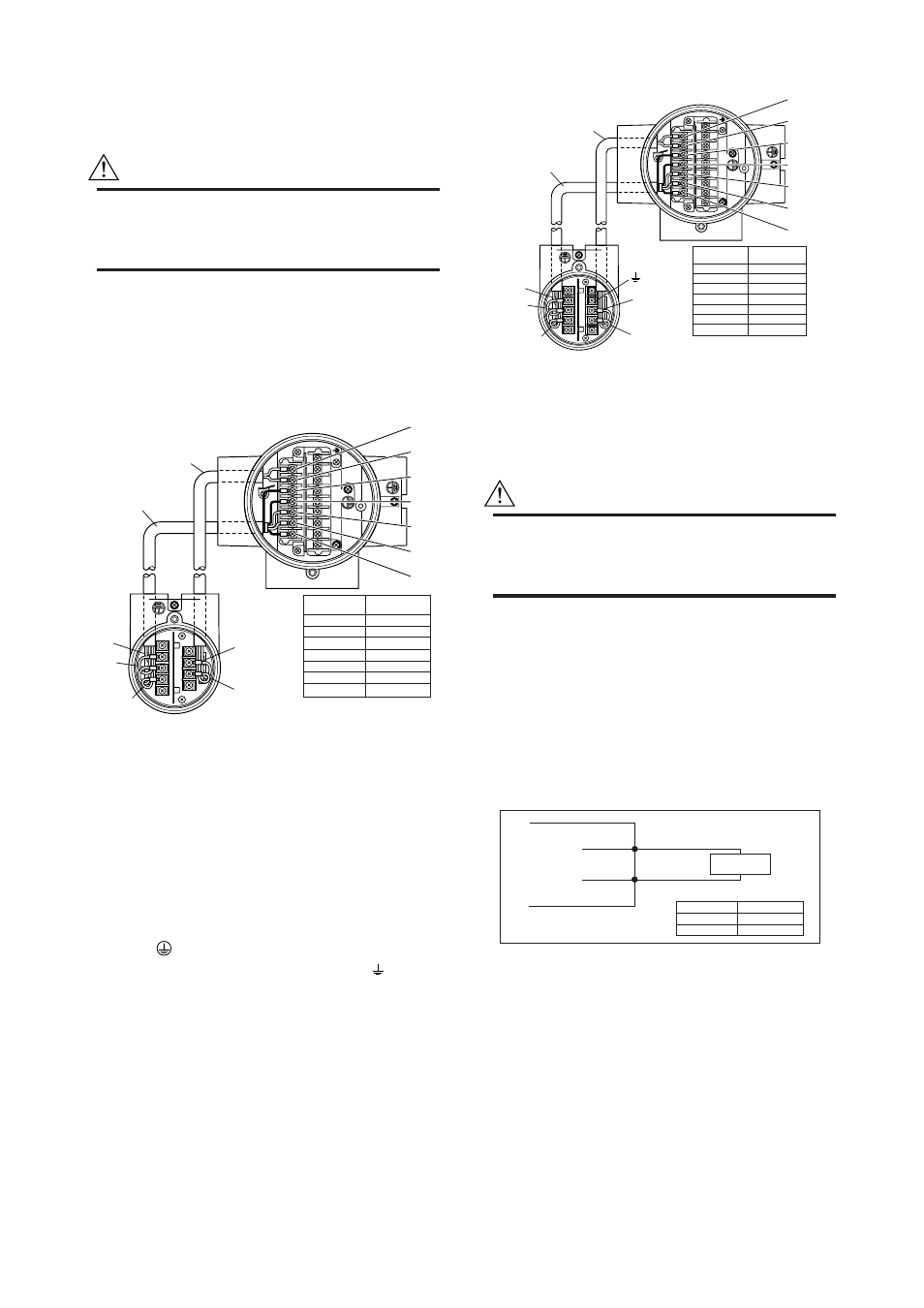
(2) Connection with the Remote Flowtube
(Explosion proof Type, Size 2.5 to 400 mm
(0.1 to 16 in.))
In case of explosion proof type for ATEX, FM, CSA,
IECEx and TIIS certification, connect wiring as shown
in the figure below.
In case of the explosion proof type, the protective
grounding
of remote flowtube must be connected to
a suitable IS grounding system. In that case,
(functional grounding terminal) need not be connected.
AXFC dedicated
signal cable
EX2
EX1
A
B
C
Excitation cable
EX1
EX2
C
SA
A
B
SB
F0414.EPS
Converter
Remote
flowtube
SA
A
B
SB
C
EX1
EX2
Taping*
A
B
Taping*
C
EX1
EX2
* Individually tape and insulate the
shields corresponding to SA and
SB on the remote flowtube side.
AXFA14 Converter
Remote flowtube
Figure 4.4.6
Wiring Diagram
4.4.7
Connecting to External Instru-
ments
WARNING
Before wiring with external instruments, be sure
to turn off the power supply for AXFA14
converter and any external instruments.
Connect the AXFA14 terminal to external instruments,
giving attention to the following points.
For F
OUNDATION
Fieldbus protocol, please refer to IM
01E20F02-01E.
For PROFIBUS PA protocol, please refer to IM
01E20F12-01E.
᭹ 4 to 20 mA DC Current Output
Resistive Load Max. 750
Ω.
Receiver
Instrument
AXFA14
l+
l-
F0415.EPS
Communication Resistive load
BRAIN
HART
250 to 450
Ω
250 to 600
Ω
Figure 4.4.7
4 to 20 mA DC Output Connection