Yokogawa EJA438 User Manual
Page 20
IM 1C22J1-01E
4-2
4. INSTALLATION
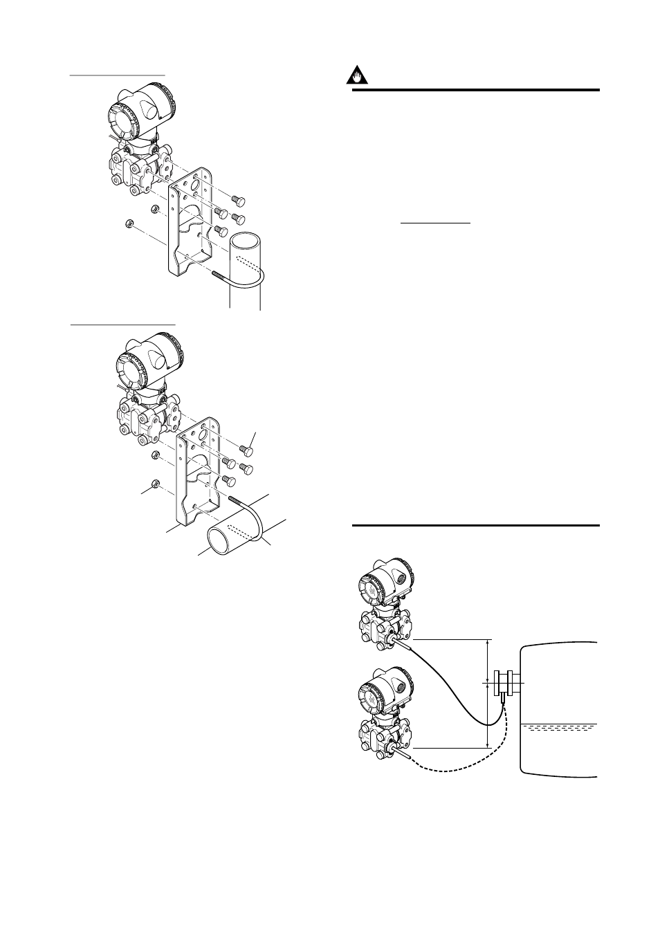
Horizontal pipe mounting
Vertical pipe mounting
Transmitter
mounting bolt
U-bolt nut
Mounting bracket
50mm (2-inch) pipe
U-bolt
F0403.EPS
Figure 4.3.1 Transmitter Mounting
IMPORTANT
The transmitter should be installed at least 700
mm (when the model code of the material of the
wetted part is H, at least 1300 mm) below the
process connection to ensure a positive head
pressure of fill fluid. If it can not be installed at
least 700 mm below the process connection,
please use the equation below:
h=
ϫ
7.5
ϫ
10
–3
[mm]
(P–P0)
ϫ
dHg
ds
h:
Vertical height between the process
connection and the transmitter (mm)
h
≤
0: Install the transmitter at least h (mm)
below the process connection
h>0: Install the transmitter at most h (mm)
above the process connection
P:
Pressure in the tank (Pa abs)
P0: Minimum working pressure limit of the
transmitter (Pa abs)
If the ambient temperature range is
–10 to 50
°
C.
5254 (Wetted parts material code S)
6980 (Wetted parts material code T)
13019 (Wetted parts material code H)
6980 (Wetted parts material code U)
ds: Specific gravity of fill fluid (at 25
°
C), refer
to GS 1C22J3-E.
dHg:Specific gravity of the Mercury 13.6 (at
25
°
C)
F0404.EPS
P
h
0
(+)
(–)
Figure 4.3.2 Example of Installation to Tank (Caution on
Installation)