Pfister 049-CNFC User Manual
Page 5
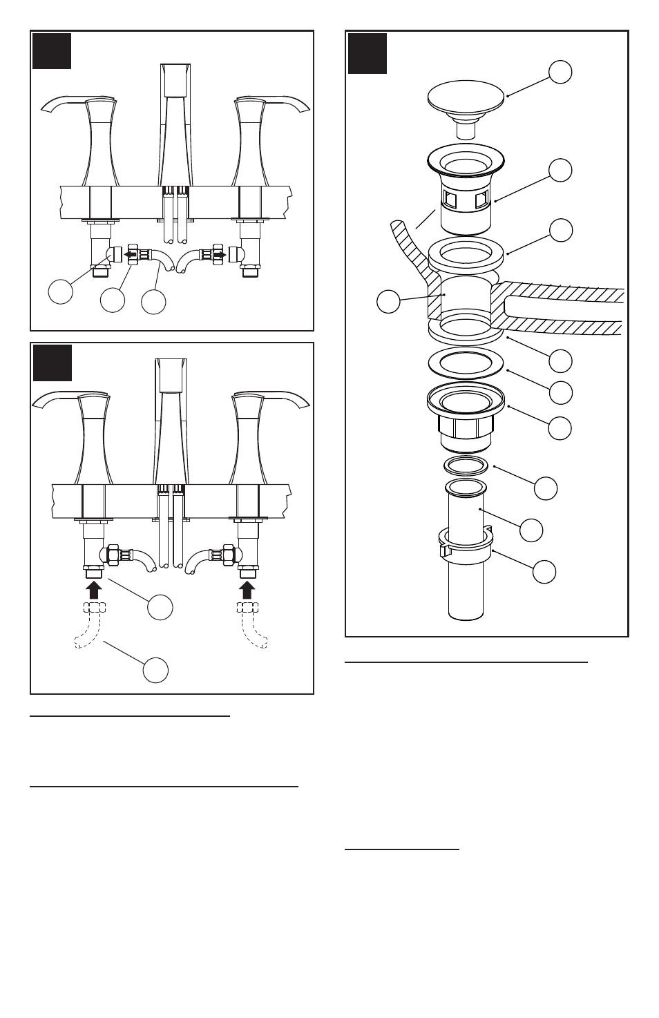
6 HOSE CONNECTIONS (Fig.C)
From underneath sink, thread Hose Couplings (1) to Valve
body Inlets (2), as shown. Carefully bend Hoses (3) to fit
available space.
7 WATER SUPPLY CONNECTIONS (Fig.D)
Connect water Supply Lines (1) to Faucet Inlets (2). Hot
water supply lines go into left inlet. Cold water supply lines
go into right inlet. (Supply lines not included). Please follow
manufacturer’s instructions when installing supply lines.
8 DRAIN BODY INSTALLATION (Fig.E)
The Flange (1) can be installed with or without Rubber Seal
(2). If Flange (1) is installed without Rubber Seal, Apply
a small bead of plumber’s putty underneath the Flange
(1) and around Drain Opening (3). Insert Flange (1) into
Drain Opening (3). From underneath, slide Rubber Washer
(4) and Round Washer (5) onto the bottom of Flange (1).
Thread Locknut (6) until Rubber Washer (4) seats securely
inside Drain Opening (3). Remove excess plumber’s putty.
Drop Stopper (7) into Flange (1). Place both Washer (8)
and Drain Tube (9) underneath Locknut (6) and secure by
tightening Nut (10).
9 UNIT START UP
Turn on hot and cold water supplies, and check for leaks
above and below the sink.
C
1
3
2
C
HOT
COLD
C
1
2
D
E
3
1
8
9
2
7
4
5
6
10
5