Acknowledge input, Thermocouple and rtd inputs, Thermostatic switch inputs – Watlow TLM-8 User Manual
Page 3: Unused inputs, Warning, Caution
WATLOW TLM-8 User’s Guide
3
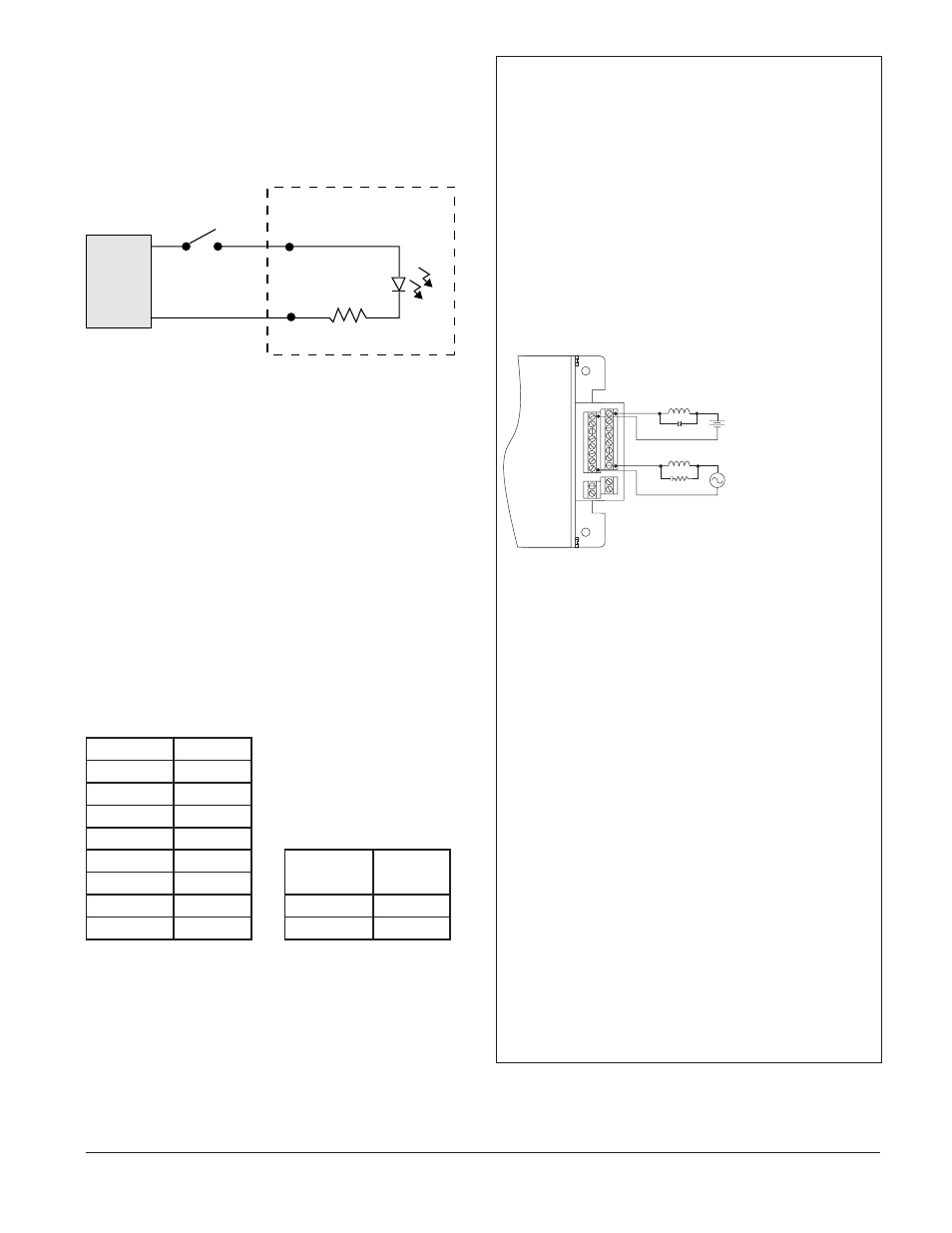
Acknowledge Input
The acknowledge input, ACK is an edge-triggered digi-
tal input. The input accepts a 5 to 30V
Î
(dc) signal.
The circuit contains a resistor and optical isolator. If
you are using a push button to generate the input sig-
nal, momentary contacts are recommended because the
input is edge-triggered.
TLM-8 Internal Circuit
ACK+
ACK–
User Supplied
Contact
DC
Power
Supply
+
_
Acknowledge Input
Thermocouple and RTD Inputs
Be sure to use the type of sensor that matches your
TLM-8; the input type is noted on the label.
Thermostatic Switch Inputs
When using thermostatic switch (thermostat) inputs,
TLM-8 trip points can be set externally. The TLM-8
should be configured for thermostatic switches. Use
normally-closed thermostats that open at or above the
trip point.
Unused Inputs
If a sensor input is not used, short the positive and
negative input terminals.
TB1 Channel Relay Outputs
Relay Output
Terminals
1 1,
2
2 3,
4
3 5,
6
4 7,
8
TB2 Global Relay Outputs
5 9,
10
Global Alarm
Output
Terminals
6 11,
12
7
13, 14
1
1, 2
8
15, 16
2
3, 4
Ó
WARNING:
You must connect the thermocouple to the input terminal
blocks correctly. If the inputs are reversed, the sensor
may be unable to generate an alarm. This could result
in a fire or other accident leading to loss of property or
lives.
Ó
CAUTION:
To protect the alarm relay contacts when connected to an
inductive load, use catch diodes for dc loads and snub-
bers on ac or dc loads. For dc applications select a diode
with a reverse breakdown voltage 10 times the applied
voltage and forward load current.
J1
CH1
CH2
CH3
CH4
CH5
CH6
CH7
CH8
NOG1
NOG2
J2
OUTPUTS
Load
Load
Back EMF Clamp
Back EMF Clamp
Wiring Recommendations for relay outputs
Ó
CAUTION:
To minimize the power dissipated by the internal circuits
and ensure temperature accuracy, apply voltage to the
ACK and TST inputs only when intending to test the TLM-8
or acknowledge alarms. At other times the applied signal
should be 0VÎ (dc).
NOTE: To avoid interference with sensor readings, sepa-
rate sensor and power wiring.
NOTE: This device is designed for indoor use only.
NOTE: Use only copper conductors for power and signals
other than thermocouples.
NOTE: Previous versions of the TLM-8 recommended
earth grounding the unit’s case, but the current version
does not require the case to be earth grounded.
NOTE: Alarm outputs and indicators are latched until the
condition is corrected and the alarm is acknowledged, as
long as the TLM-8 remains powered. If power is cycled to
the unit, it will evaluate the limits again.