Mounting the tlm-8, Wiring recommendations, Din rail mounting – Watlow TLM-8 User Manual
Page 2: Din rail removal, Panel mounting, Dc power supply, Test input
2
WATLOW TLM-8 User’s Guide
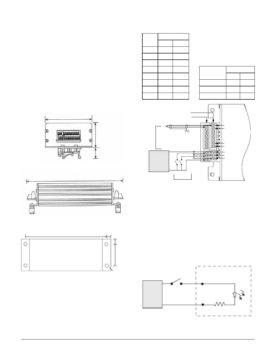
Mounting the TLM-8
The TLM-8 mounts directly to a panel or on a DIN rail
depending on the mounting style ordered.
DIN Rail Mounting
The TLM-8 simply snaps onto a standard 35 mm DIN
rail. Place the hook side of the mounting mechanisms
over one of the DIN rail edges and snap the assembly
over the other edge.
DIN Rail Removal
Remove the TLM-8 from the DIN rail by placing a flat
blade screw driver through the slot in the end plate,
hook the blade into the snap latch and pry the snap
latch away from the DIN rail edge. Repeat for the other
side.
92 mm (3.61 in)
48 mm
(1.87 in)
20 mm
(0.75 in)
End View
236 mm (9.30 in)
Side View
NN JO
NN
JO
NN
JO
NN
JO
NN
JO
Mounting Hole Dimensions
Panel Mounting
The four mounting holes will accommodate up to 3.8
mm (#6) screws or bolts.
Wiring Recommendations
TB5 Sensor Inputs
Sensor
Input
Terminals
+
-
1
1
2
2
3
4
TB6 Power and Digital
Inputs
3
5
6
4
7 8
Function
Terminals
5
9
10
+
-
6
11 12
Test
1
2
7
13 14
Acknowledge
3
4
8
15 16
Power
5
6
SENSOR
J6
1
2
3
4
5
6
7
8
TST
-
V
-
J5
ACK-
Positive Terminals
Negative Terminals
Sensor
Inputs
Test and
Acknowledge Circuits
Channel 1
Channel 2
.
.
.
.
Channel 7
Channel 8
TST
ACK
Power
Isolated
DC Power
supply
+
_
Input Wiring
DC Power Supply
The TLM-8 accepts 12 to 24V
Î
(dc) power input from a
class 2 power supply.
Test Input
The test input, TST, is a level-triggered digital input. It
is activated after the input signal is applied for at least
1 second (filter). The input signal may be generated by
a contact closure or controller output. The input accepts
a 5 to 30VÎ (dc) signal. The circuit contains a resistor
and optical isolator.
5-.*OUFSOBM$JSDVJU
545
545m
6TFS4VQQMJFE
$POUBDU
%$
1PXFS
4VQQMZ
@
Test Input