Input wiring, Thermocouple, Rtd (2- or 3-wire) 100platinum – Watlow Series V4T User Manual
Page 6: Process, Process,4-20ma, Process,0-5v î (dc), V dc, I dc, Figure 6a, Figure 6b
6
Wa t l o w S e r i e s V 4
Input Wiring
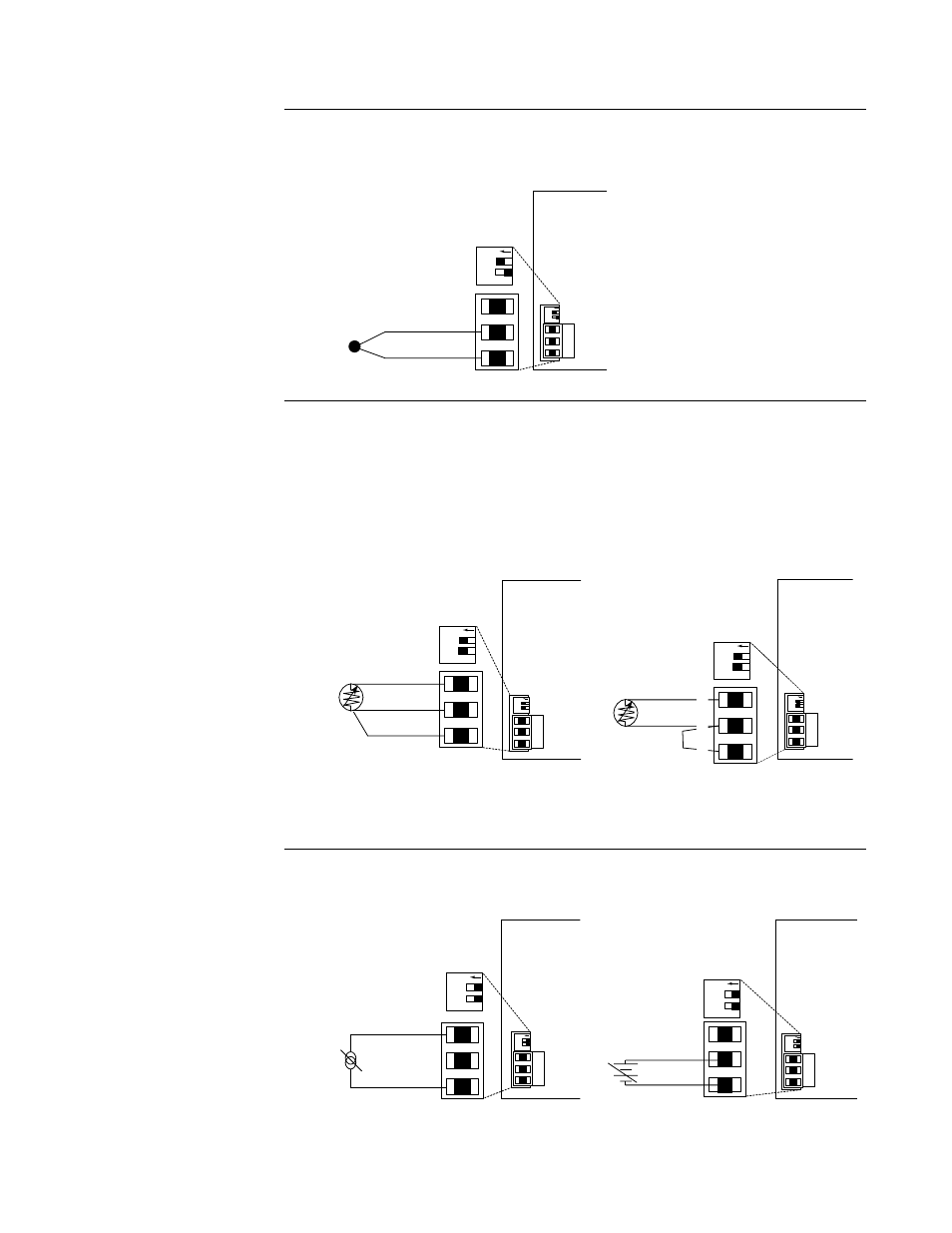
Figure 6a –
Thermocouple
Extension wire for thermocouples must be of the same alloy as the thermo-
couple itself to limit errors.
Figure 6b –
RTD (2- or 3-Wire) 100
Ω Platinum
There could be a +2°F input error for every 1
Ω of lead length resistance
when using a 2-wire RTD. That resistance, when added to the RTD element
resistance, will result in erroneous input to the instrument. To overcome
this problem, use a 3-wire RTD sensor, which compensates for lead length
resistance. When extension wire is used for a 3-wire RTD, all wires must
have the same electrical resistance (i.e. same gauge, same length, multiple-
stranded or solid, same metal.
Figure 6c –
Process,4-20mA
Figure 6d –
Process,0-5VÎ (dc)
Input impedance: 5
Ω
Input impedance: 10k
Ω
DIP Switch
Orientation
DIP Switch
Orientation
1: ON
2: ON
PROC
-
+
V dc
4
5
6
5
6
OFF
1 2
OFF
1 2
-
4
+
6
I dc
PROC
DIP Switch
Orientation
1: ON
2: ON
DIP Switch
Orientation
OFF
1 2
4
5
6
OFF
1 2
2-wire RTD
Jumper Terminals 5 & 6
(customer supplied)
S1
S2
S3
4
5
6
DIP Switch
Orientation
DIP Switch
Orientation
1: OFF
2: OFF
RTD
OFF
1 2
4
5
6
OFF
1 2
OFF
1 2
3-wire
RTD
S1
S2
S3
4
5
6
DIP Switch
Orientation
DIP Switch
Orientation
1: OFF
2: OFF
RTD
4
5
6
OFF
1 2
DIP Switch
Orientation
TC
T/C
+
-
5
6
DIP Switch
Orientation
1: OFF
2: ON
OFF
1 2
4
5
6
OFF
1 2
NOTE:
Successful installa-
tion requires five
steps:
• Choose the con-
troller’s hardware
configuration and
model number;
• Choose a sensor;
• Install the con-
troller;
• Wire the controller
and
• Configure the con-
troller.
ç
WARNING:
To avoid damage to
property and equip-
ment and/or injury or
loss of life, use
National Electric
Code (NEC) standard
wiring practices to
install and operate
this unit. Failure to
do so could result in
injury and/or death,
or such damage.
NOTE: When an
external device with a
non-isolated circuit
common is connect-
ed to the 4-20mA or
dc output, you must
use an isolated or
ungrounded thermo-
couple.
ç
CAUTION: Process
input does not have
sensor break protec-
tion. Outputs can
remain full on.