How to set up the series v4, Entering the setup menu – Watlow Series V4T User Manual
Page 12
Wa t l o w S e r i e s V 4
1 2
Setting up the Series V4 is a simple process. First set the DIP switches to match
your input type. Refer to the orientation on the back of the controller to select the
[``In] Input value. Next, configure the Series V4's features to your application
in the Setup Menu, then enter values in the Operating Menu. Both tasks use the
‰Advance key to move through the menus and the Up-arrow/Down-arrow keys to
select data.
Before entering information in the Setup Menu, set the [`dFL] parameter. If
[``SI] is selected, °C, proportional band in % of span, derivative and integral are
the defaults. If [``US] is selected, °F, proportional band in degrees, reset and rate
are the defaults. Changing the [`dFL] prompt will set parameters to their
factory default. Document all current parameter settings first. See the cal-
ibration section in the Appendix to change this parameter.
Entering the Setup Menu
The Operation Menu will appear as the default menu of the Series V4. The
Setup Menu displays the parameters that configure the Series V4's features to
your application.
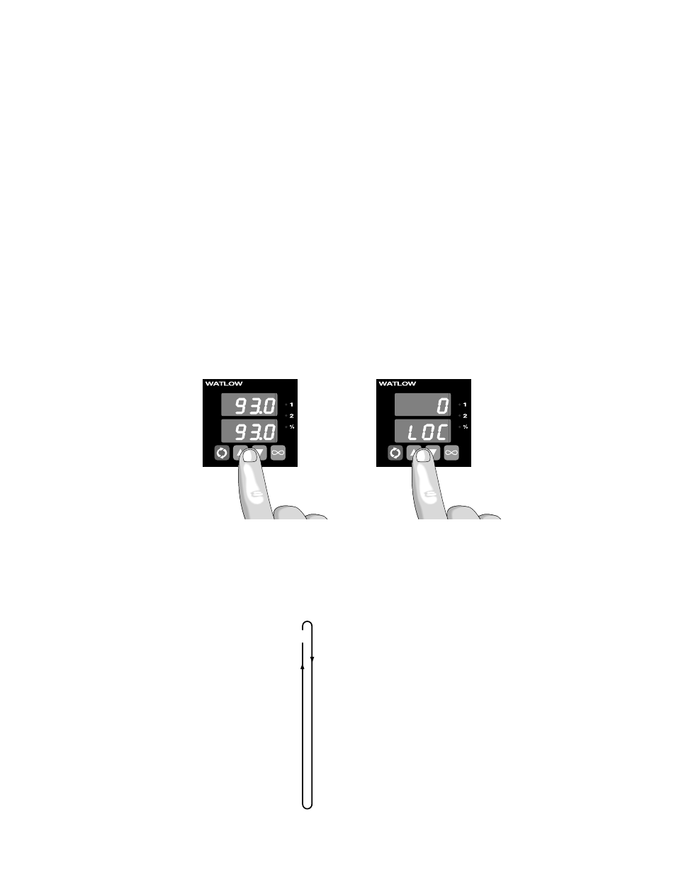
Enter the Setup Menu by pressing the ¿Up-arrow and ¯Down-arrow keys si-
multaneously for 3 seconds. The lower display shows the [`LOC] Lock parame-
ter, and the upper display shows its current level. All keys are inactive until you
release both keys. You can reach the Lock parameter from anywhere.
Use the ‰Advance key to move through the menus and the ¿Up-arrow and
¯Down-arrow keys to select data. You will not see all parameters in this menu,
depending on the controller's configuration and model number. After stepping
through the menu it returns to the set point parameter under the Operation
Menu. If no keys are pressed for approximately 60 seconds, the controller
returns to the default display, Process over Set Point.
93
93
∫
WARNING:
Remove power from the
controller before remov-
ing the chassis from the
case or changing the DIP
switches. Removing the
controller from the chas-
sis is not a normal oper-
ating condition and
should only be done by a
qualified technician.
How to Set Up the Series V4
Figure 12a -
Entering the Setup Menu.
Figure 12b -
The Setup Menu.
NOTE:
While in the Setup
Menu, all outputs are off.
[`LOC] Lock
[``In] Input
[`dEC] Decimal*
[`C_F] Celsius - Fahrenheit*
[``rL] Range Low
[``rH] Range High
[`Ot1] Output 1
[`HSC] Hysteresis Control
[`Ot2] Output 2
[`HSA] Hysteresis Alarm*
[`LAT] Latching*
[`SIL] Silencing*
[`rtd] RTD*
[`rP`] Ramping
[`rT`] Rate*
[`P`L] Power Limiting*
[`dSP] Display
* Parameter may not always appear.
‰
Setup Menu