Specifications, Ordering information, Watlow controls 8 ehg cl user’s guide – Watlow Series EHG CL User Manual
Page 8: Power, No-arc relay, Environmental, Agency approvals, Warranty, Wiring the series ehg cl communications ports
Watlow Controls
8
EHG CL User’s Guide
Specifications
Power
• Isolated Universal Power Supply: 85 to 264V
Å (ac)
50/60Hz
• Up to 2400 W with 10A switching capability
NO-ARC Relay
• 10A
switching
• 4.5 million cycles
Environmental
• Ambient operating temperature range 0 to 70 °C (32 to
158 °F)
Agency Approvals
• UL
®
1998/C-UL
®
• CE
60730
• SEMI-S2
Ordering Information
Series EHG CL Integrated Temperature Controller
- EHG2-AAAA-_ _ _ _ 0 to 537°C (0 to 999°F)
- Display Module - EHG2-CLOO-COMS
- Communications Module - EHG2-CLOO-COMS
- Display with Communications Module - EHG2-CLOO-DSCM
Additional Power Cables
- 4800-0012: jumpered long cable
- 4800-0022: terminated long cable
- 4800-0011: jumpered short cable
- 4800-0021: terminated short cable
Warranty
The Series EHG CL is warranted to be free of defects in material and
workmanship for 24 months after delivery to the first purchaser for
use, providing that the units have not been misapplied. Since Watlow
has no control over their use, and sometimes misuse, we cannot guar-
antee against failure. Watlow’s obligations hereunder, at Watlow’s
option, are limited to replacement, repair or refund of purchase price,
and parts which upon examination prove to be defective within the
warranty period specified. This warranty does not apply to damage
resulting from transportation, alteration, misuse or abuse.
WARNING:
To avoid damage to property and equipment, and/or injury
or loss of life, use National Electric Code (NEC) standard
wiring practices to install and operate the Series EHG CL.
Failure to do so could result in such damage, and/or injury
or death.
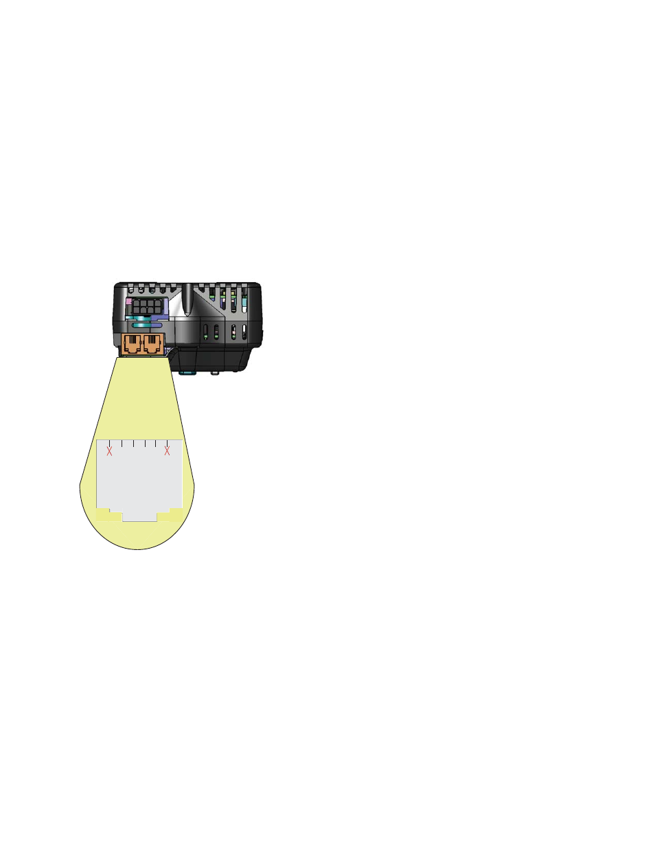
Wiring the Series EHG CL Communications Ports
The graphic below reflects the control being held upright
with the display facing the holder. As shown, there are
two jacks on the top of the communications module (RJ45
like, with 4 pins on each) which can accommodate either
a four or six 6 pin modular plug. Communications from
a PC to any EHG CL controller on the network can be
established by connecting it to either of the two available
jacks. The other jack can then be connected to other EHG
CL controllers on the network (32 maximum).
Looking at either of the jacks as shown in the graphic pin
identification is from left to right.
- Left most pin, connects to ground terminal of converter
- Second pin from left, no connection
- Third pin from left, connects to converter A or T- / R-
- Right most pin connects to converter B or T+ / R+
1
2
3
4 5
6
Gnd t
erminal of c
on
ver
te
r
No c
onnec
tion
A or
T- / R-
B or
T+ / R+