Alarm wiring, Changing the position of an alarm jumper – Watlow Series 945 High/Low Limit Control User Manual
Page 6
6
WATLOW Series 945 High/Low Limit User's Manual
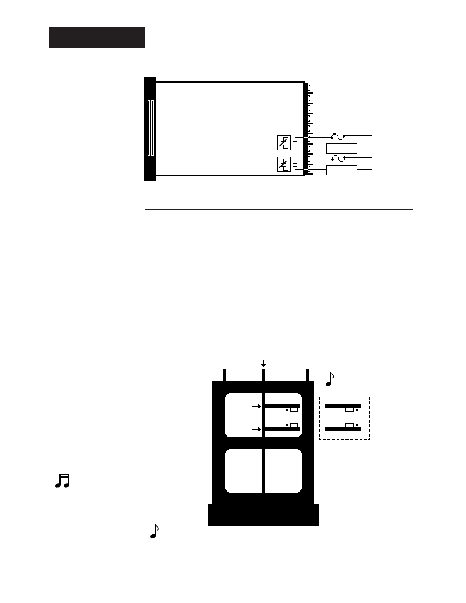
Alarm Wiring
Off state impedance is 20K
Ω
minimum.
945A- _ _ _
2
- _ 000
Figure 9 -
Alarms Option
Wiring Diagram.
Alarm Outputs, Form A or B, 6 Amp Mechanical Relay
Changing the Position of an Alarm Jumper
Whenever you change the position of a jumper, follow this procedure:
1. Remove power from the Series 945. Turn the front panel screw 90
°
counterclockwise.
2. Grip the front panel bezel and pull it straight out from the control case. The
control chassis will come out of the case as you pull the bezel.
3. Set the jumper to the position you want. See Figure 10 for jumper location.
4. Return the control chassis to the case. Be sure you have it oriented
correctly. It will not fit in upside down, but check just the same. Press
firmly, but gently, to seat the chassis.
Figure 10 -
Alarms Jumper
Location.
NOTE:
Depending on the
unit you order, your
control may have 0,
1, or 2 alarm jump-
ers.
NOTE:
The alarm output de-energizes upon an alarm or power interruption to the 945's power
supply. When you select N.O. Contacts, the contact is open when an alarm occurs.
When selecting N.C. Contacts, the contact closes when an alarm occurs.
A007-1828
Options Board
A007-1789
N.C.
Contacts
(Form B)
Control Chassis - Top View
N.O.
Contacts
(Form A)
Alarm 1
Fuse
L1
L2
26
27
Alarm 2
Fuse
L1
L2
24
25
AL2
AL2
AL2
AL2
Output 3
Output 2
Output 3
Output 2