Power wiring, How to wire the series 945 – Watlow Series 945 High/Low Limit Control User Manual
Page 3
3
WATLOW Series 945 High/Low Limit User's Manual
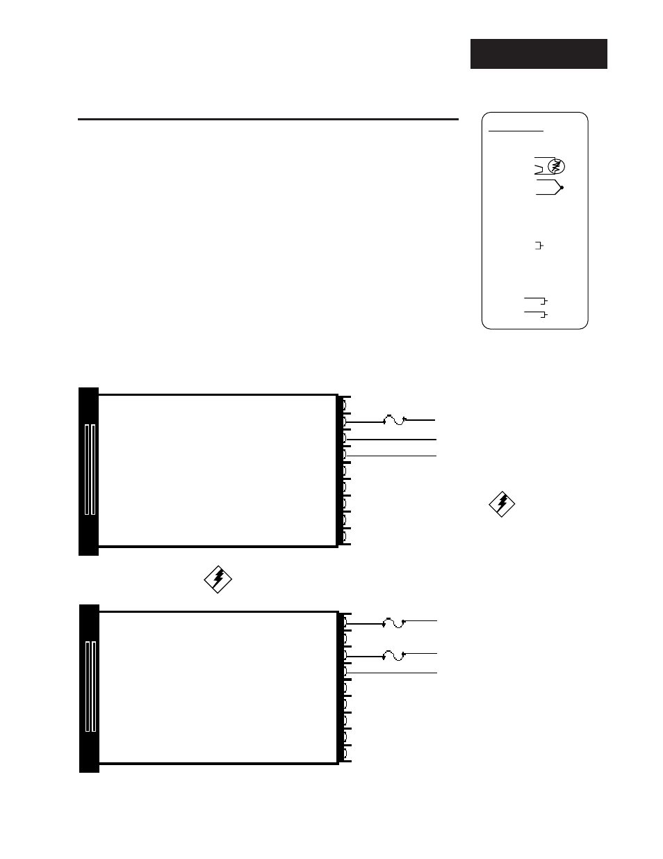
Power Wiring
L1
Fuse
L2
Earth Ground
11
12
13
L1
Fuse
L2
Earth Ground
10
12
13
Fuse
120 VAC
240 VAC
WARNING:
To avoid potential
electric shock, use
National Electric
Code (NEC) safety
practices when
wiring and connect-
ing this unit to a
power source and to
electrical sensors or
peripheral devices.
Figure 2 -
120 VAC Power
Wiring
Figure 3 -
240 VAC Power
Wiring
How to Wire the Series 945
The Series 945 wiring is illustrated by model number option. Check the unit
sticker on the control (see right) and compare your model number to those
shown here and also the model number breakdown in the Appendix of this
manual.
Series 945 internal circuits appear "inside" the line drawing of the 945, while
connections and terminal designations appear "outside" the line drawing. All
outputs are referenced to a de-energized state. The final wiring figure is a
typical system example.
When you apply power without sensor inputs on the terminal strip, the Series
945 will display "- - - -" in the Upper display, and a "0" in the Lower display.
Press the ALARM CLEAR key twice, and an ER 7 is displayed for one second.
This error indicates an open sensor or A/D error. Remove power to the control
and connect the sensor properly, see Page 4 and 5. All wiring and fusing must
conform to the National Electric Code and to any locally applicable codes.
1 4-20, 0-5 +
2 4-20, Jumper to 3
3 4-20, 0-5 -
4 S1 RTD
5 S2 RTD
6 S3 RTD
7 T.C. +
8 Not Used
9 T.C. -
10 L1 240V
11 L1 120V
12 L2
13 Earth Ground
14 Not Used
15 Not Used
16 DC -
17 DC +
18 Not Used
19 Not Used
20 Not Used
21 Not Used
22 Not Used
23 Not Used
24 Com.
25 N.O. or N.C.
26 Com.
27 N.O. or N.C.
Terminal Function
Output #1
Alarm #2
945A-2CA2-AJAP
Alarm #1