System wiring example, System example, Figure 13 - system wiring example – Watlow Series 365 User Manual
Page 9
WATLOW Series 365 User’s Manual
9
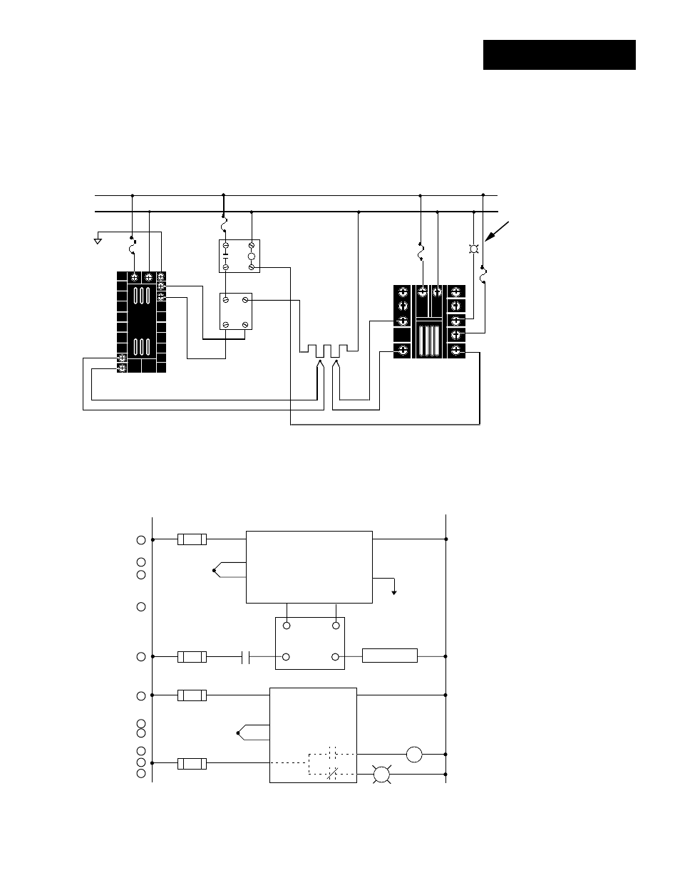
System Example
Figure 13 -
System Wiring
Example
988A-10CA-AARR
Rear View
(+)
1 0
9
2 2
2 1
1 2
1 3
(-)
L1
L2
(-)
120 VAC
Fuse
365D-D601-1000
Limit Control
Heater
Process Sensor
Limit Sensor
Red
High Limit
Mechanical
Contactor
Earth Ground
(+)
DC Input
SSR
SSR-240-10G-DC1
In
Out
1
2
4
3
Coil
1 1
(+)
5
3
1 2
1 1
9
1 0
(-)
N.O.
Red
Com
8
Indicator on
when limit trips
N.C.
1
120VAC
L1
L2
2
9
10
4
5
1
2
1
2
(+)
(-)
3
12
17
13
14
2
1CR
15
Hi Temp. Light
1
2
3
4
8
9
10
11
R
SSR-240-10G-DC1
DC Input Solid State Relay
16
1
9
Heater
Out
24-240VAC
(+)
(-)
3-32VDC
In
1 CR-1
10
11
2
12
13
7
8
21
22
5
6
7
Limit Control
Series 988
988A-10CA-AARR
Temperature control
Series 365
365D-D601-1000
9
10
8
5
11
12
3
(+)
(-)
11
6
See also other documents in the category Watlow Sensors:
- 12LS Controller (111 pages)
- 8LS Controller (140 pages)
- 8PID Controller (55 pages)
- Addendum to EZwarePlus (50 pages)
- ANASCAN (62 pages)
- ANASOFT (95 pages)
- ANAWIN 2 (154 pages)
- ANAWIN 3 (23 pages)
- Calibrating Watlow Series 988 Family Process Controls (19 pages)
- CAS (98 pages)
- CAS200 (124 pages)
- CLS (180 pages)
- CLS200 (251 pages)
- CLS200, MLS300 and CAS200 (92 pages)
- Control Console (12 pages)
- CPC400 (230 pages)
- DIN-A-MITE Style A (9 pages)
- DIN-A-MITE Style B (14 pages)
- DIN-A-MITE Style C (22 pages)
- DIN-A-MITE Style D (9 pages)
- DIN-Mount Adapter Instruction Sheet, Rev A (1 page)
- Dual DAC (4 pages)
- EM Gateway (28 pages)
- E-Safe Hybrid Relay Rev B (4 pages)
- E-SAFE II Hybrid Power Switch (4 pages)
- EZwarePlus Programming (264 pages)
- EZ-ZONE PM (111 pages)
- EZ-ZONE PM PID (125 pages)
- EZ-ZONE PM Express Limit (34 pages)
- EZ-ZONE PM Express (35 pages)
- EZ-ZONE PM Integrated Controller (181 pages)
- EZ-ZONE RM Limit Module Rev C (127 pages)
- EZ-ZONE RMA Modul (79 pages)
- EZ-ZONE RMC (236 pages)
- EZ-ZONE RME (124 pages)
- EZ-ZONE RMH (161 pages)
- EZ-ZONE RUI/Gateway (62 pages)
- EZ-ZONE RM-Scanner-Modul (140 pages)
- EZ-ZONE ST (97 pages)
- F4 External Event Board - Rev.B (2 pages)
- HG Series Mercury Displacement Relay (6 pages)
- LogicPro (296 pages)
- Mercury Relay or MDR Retrofit (13 pages)
- MICRODIN (106 pages)
- MICRODIN (24 pages)