Power/switches, Internal heat/cool switch location, Power wiring – Watlow Series 365 User Manual
Page 6: Reset switch, Reset switch, customer supplied
6
WATLOW Series 365 User’s Manual
Power/Switches
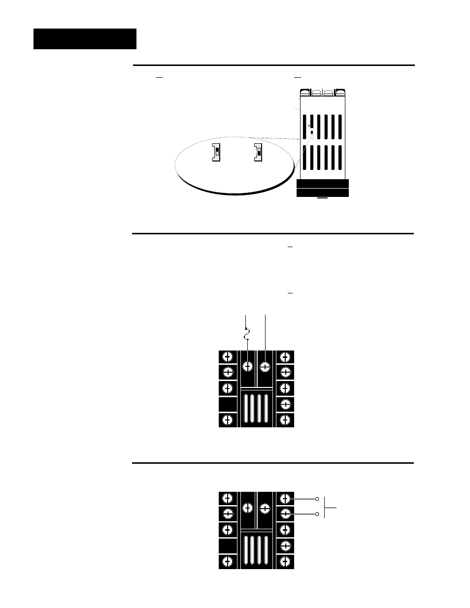
Fuse
L1
L2
1 1
1 2
N.O.
Momentary
Reset Switch
6
7
Figure 6 -
120 and 240VAC
Power Wiring
Figure 5 -
Heat/Cool Switch
Settings
Power Wiring
100/120VAC
3 6 5 _ - _ _ _ _ - 1 0 0 0
and
208/240VAC
3 6 5 _ - _ _ _ _ - 2 0 0 0
Reset Switch, Customer Supplied
Limit versions only
Internal Heat/Cool Switch Location
3 6 5 A - _ _ _ _ - _ 0 0 0 and
3 6 5 B - _ _ _ _ - _ 0 0 0
l
NOTE:
The line voltage is
determined by your
model number.
k
NOTE:
Removing the
Series 365 chassis
from its case will
make changing the
Heat/Cool switch
easier.
Figure 7 -
Reset Switch Wiring
(Customer Supplied)
l
k
Bottom View
Heat/Cool
Switch
Heat Mode
(switch toward
the back of
the control)
Cool Mode
(switch toward
the front of
the control)
See also other documents in the category Watlow Sensors:
- 12LS Controller (111 pages)
- 8LS Controller (140 pages)
- 8PID Controller (55 pages)
- Addendum to EZwarePlus (50 pages)
- ANASCAN (62 pages)
- ANASOFT (95 pages)
- ANAWIN 2 (154 pages)
- ANAWIN 3 (23 pages)
- Calibrating Watlow Series 988 Family Process Controls (19 pages)
- CAS (98 pages)
- CAS200 (124 pages)
- CLS (180 pages)
- CLS200 (251 pages)
- CLS200, MLS300 and CAS200 (92 pages)
- Control Console (12 pages)
- CPC400 (230 pages)
- DIN-A-MITE Style A (9 pages)
- DIN-A-MITE Style B (14 pages)
- DIN-A-MITE Style C (22 pages)
- DIN-A-MITE Style D (9 pages)
- DIN-Mount Adapter Instruction Sheet, Rev A (1 page)
- Dual DAC (4 pages)
- EM Gateway (28 pages)
- E-Safe Hybrid Relay Rev B (4 pages)
- E-SAFE II Hybrid Power Switch (4 pages)
- EZwarePlus Programming (264 pages)
- EZ-ZONE PM (111 pages)
- EZ-ZONE PM PID (125 pages)
- EZ-ZONE PM Express Limit (34 pages)
- EZ-ZONE PM Express (35 pages)
- EZ-ZONE PM Integrated Controller (181 pages)
- EZ-ZONE RM Limit Module Rev C (127 pages)
- EZ-ZONE RMA Modul (79 pages)
- EZ-ZONE RMC (236 pages)
- EZ-ZONE RME (124 pages)
- EZ-ZONE RMH (161 pages)
- EZ-ZONE RUI/Gateway (62 pages)
- EZ-ZONE RM-Scanner-Modul (140 pages)
- EZ-ZONE ST (97 pages)
- F4 External Event Board - Rev.B (2 pages)
- HG Series Mercury Displacement Relay (6 pages)
- LogicPro (296 pages)
- Mercury Relay or MDR Retrofit (13 pages)
- MICRODIN (24 pages)
- MICRODIN (106 pages)