Proface FP3900 - 19 Flat Panel" User Manual
Page 8
8
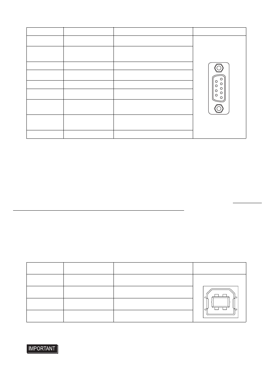
Pin Assignments and Signal Names for Serial Interface
Connector...........................Dsub 9 pin female
Connector set screw ..........#4-40 UNC
Cable ..................................SIO cable for FP manufactured by Pro-face.
(FP61V-IS00-O)
Concerning Signal Names
Signal names used for the serial interface on FP units are designed to match the pin order used
on most PC serial interfaces, so that a straight cable can be used to connect the two. Therefore,
connect each pin’s signal to the same signal name on the PC side.
For example, pin #2 ‘RD’ should be connected to the ‘RD’ input terminal on the PC’s connector.
Refer to the FP3000 Series User Manual’s section “Cable Diagrams” for each signal’s direction.
USB Interface (Type-B connector : Up-Stream Port)
Pin Assignments and Signal Names for USB Interface
Cable ..................................USB cable manufactured by Pro-face.
(FP-US00)
Pin No.
Signal Name
Condition
Pin Location
1
CD
Carrier Detect
*1
*1 The CD, DTR, and DSR are connected together inside of the FP.
2
RD
Receive Data (FP->
Host)
3
SD
Send Data (FP<-Host)
4
DTR
Data Terminal Ready
5
GND
Ground
6
DSR
Data Set Ready
7
RS
Request to Send (FP<-
Host)
8
CS
Clear to Send (FP->
Host)
9
NC
(Used internally)
Pin No.
Signal Name
Condition
Pin Location
1
USB1-5V
+5VIN
2
USBD1(-)
USB data(-)
3
USBD1(+)
USB data(+)
4
GND
Ground
• If a cable other than the specified USB cable is used, product
performance cannot be guaranteed due to the possibility of
noise interfering with the FP unit’s operation.
6
9
1
5
4
3
2
1