Series 80 spool valve construction, Manual overrides, Valve response time – Ross Controls POPPET SERIES 84 User Manual
Page 2: Flow ratings, Port identification
4
© 2012, ROSS CONTROLS
®
. All Rights Reserved.
STANDARD SPECIFICATIONS (for valves on page 5):
Solenoids: AC or DC power. Rated for continuous duty.
Standard Voltages:
SAE Size 125, 250 models: 100-110 volts, 50 Hz; 100-120 volts, 60
Hz; 24 volts DC; 110 volts DC. For other voltages, consult ROSS.
SAE Size 500 models: 100-110 volts, 50 Hz; 100-120 volts, 60
Hz; 24 volts DC; 110 volts DC. For other voltages, consult ROSS.
Power Consumption: Each solenoid:
SAE Size 125, 250 models: 8 VA inrush; 6 VA holding on 50/60
Hz; 8 watts on DC.
SAE Size 500 models: 87 VA inrush; 30 VA holding on 50/60 Hz;
14 watts on DC.
Indicator Light: One for each solenoid.
Ambient Temperature: 40° to 120°F (4° to 50°C).
Media Temperature: 40° to 175°F (4° to 80°C).
Flow Media: Filtered air; 5 micron recommended.
Inlet Pressure: Vacuum to 150 psig (10 bar).
Pilot Pressure: At least 15 psig (1 bar).
Options: Pressure Controlled Valves–Interposed Pressure
Regulators.
MANUAL OVERRIDES
Each solenoid pilot has a non-locking override button for manual actuation of
the valve. For Size 500 valves, locking buttons and extended buttons are also
available. See page 9.
VALVE RESPONSE TIME
Average response constants for each valve are listed in the charts on pages
4 thru 6. These constants, designated M and F, can be used to determine the
amount of time required to fill or exhaust a volume of any size by using the
following formula:
Valve Response Time (msec) = M + (F • V)
In this formula, M represents the average time in milliseconds (msec) for
the valve parts to move after the valve is energized. F is the average number
of milliseconds required for a flow of one standard cubic inch through the valve.
V is the number of cubic inches in the volume to be filled or exhausted.
The valve response time given by this formula is the average number of
milliseconds required to fill the volume V to 90 per cent of supply pressure, or
to exhaust the volume to 10 per cent of supply pressure. Response times will
be valid for any pressure in the range specified for the valve under "Standard
Specifications."
Note that F values are listed under two headings: "In-Out" and "Out-Exh."
The In-Out values are used to calculate fill times, and the Out-Exh. values are
used to calculate exhaust times.
SAMPLE PROBLEM. Using a ROSS double solenoid size 250 poppet valve,
how long will it take to fill a 250-cubic-inch chamber to 90% of supply pressure?
SOLUTION. The poppet valves are described on page 4 of this bulletin. From
the chart at the bottom of the page, we find that the response constants for a
size 250 valve are M = 20 and F = 0.54. Using these values in the response
time formula we have:
Valve Response Time (msec) = 20 + (0.54)(250)
= 20 + 135
= 155 msec
FLOW RATINGS
IMPORTANT NOTE. Widely different test standards are used by different
manufacturers in the determination of Cv ratings of valves. For this reason,
the Cv values given in the charts on pages 4, 5, and 6 should not be used in
comparing ROSS valves with those of other makers. These Cv values are
intended only for use with performance charts published by ROSS.
The Cv ratings in the charts on pages 4, 5, and 6 are averages for the various
flow paths through the valve and are for steady flow conditions.
PORT IDENTIFICATION
Ports on bases and in diagrams are designated by the following letters:
P: Inlet port
A: Outlet port
B: Outlet port
EA: Exhaust port (from port A)
EB: Exhaust port (from port B)
X: External pilot supply port
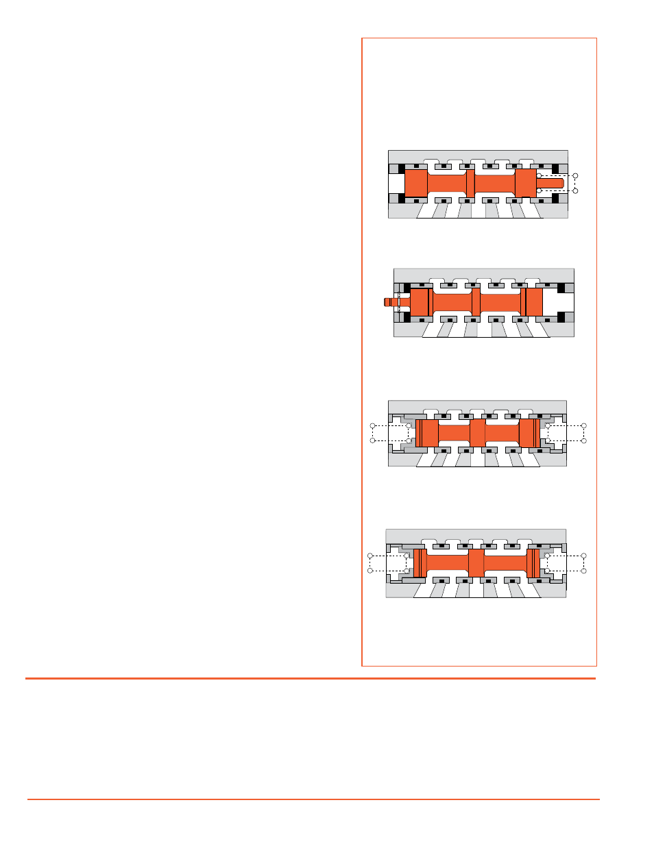
SERIES 80
Spool Valve Construction
The matched spool and sleeve used in each of these
valves is made of precision finished, hardened, stain-
less steel. The spool moves on a micro-inch film of air
between spool and sleeve so that wear is minimized.
For use in systems with or without air line lubrication.
Open Center, Double Control. 5-port, 3-position
(5/3) valves require a maintained signal to shift the
valve in either direction from center. In the center
position the outlet ports are connected to the exhaust
ports and the inlet port is closed.
Single Control. 5-port, 2-position (5/2) valves require
a maintained signal to keep the valve shifted. A spring
provides the return force after the signal is removed.
Double Momentary Control. 5-port, 2-position (5/2)
valves require only a momentary signal to shift the
valve in either direction. A mechanical detent keeps
the valve in its shifted position.
Closed Center, Double Control. 5-port, 3-position
(5/3) valves require a maintained signal to shift the
valve in either direction from center. In the center
position all ports are closed.