Gear – Ramsey Winch RPH-25000 User Manual
Page 9
9
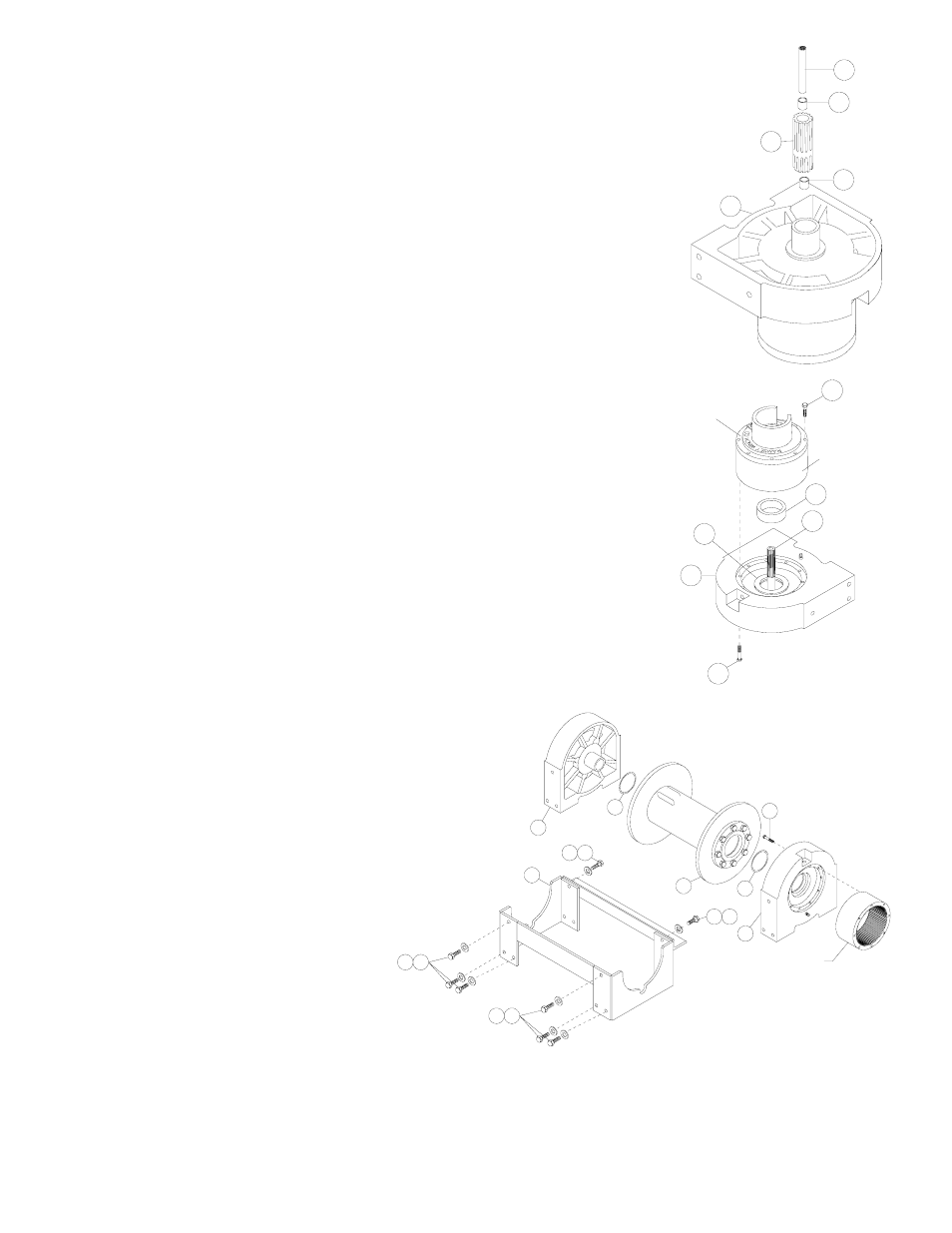
6. Remove output coupling (item #7) and coupling shaft (item #6) from end bearing (item
#9). Examine bearings (item #13), pressed in output coupling (item #7), for signs of
wear. Replace bearings, if necessary, by pressing old bearings from coupling and press
new bearings (item #13) into each end of output coupling (item #7). Place coupling
shaft (item #6) into bearings (item #13).
7. Remove (8) capscrews (item #15) to pull gear-housing cover from ring
gear
. Remove input thrust washer, sun gear, carrier assemblies, and
spacer (item #13) from inside of ring gear. Examine splines of ring gear
and if necessary, remove ring gear from end bearing (item #9) by
removing (12) capscrews (item #16). Examine bushing (item #14) for
signs of wear. Replace bushing, if necessary, by pressing old bushing
from housing and pressing new bushing into place.
Apply RTV sealing compound to ring gear-mounting surface of end bearing
(item #9). Place ring gear onto end bearing, aligning holes in ring gear with
holes and gear housing end bearing. Secure ring gear to end bearing using
(12) capscrews (item #16). Torque to 40 ft-lbs, each in a criss-cross pattern.
Examine shifter shaft (item #12) for signs of wear, replace if necessary.
8. NOTE: DETERMINE MOUNTING CONFIG-
URATION OF WINCH (R.H. or L.H.
MOUNTED) BEFORE ATTACHING FRONT
AND REAR FRAME ASSEMBLY TO WINCH,
TO ASSURE PARTS ARE MOUNTED TO
PROPER SIDE, REFER TO WINCH
MOUNTING CONFIGURATIONS, PAGE 6.
Seat well-oiled quad-rings (item #38 &
#39) into groove of bushing in each end of
drum assembly (item #2), as shown.
Carefully set drum assembly (item #2)
down over motor end bearing (item #9). Lift
gear-housing end bearing (item #9) and set
into place on drum assembly. Install frame
assembly (item #1) using capscrews and
lockwashers shown below. Tighten (4)
capscrews securely, check rotation of cable
drum.
9
6
7
14
14
GEAR HOUSING
COVER
9
15
12
RING GEAR
21
13
22
RING GEAR
25
16
16 25
1
8
39
17 25
17 25
2
9
40
22