Typical layout, Hydraulic system requiremnts, Performance charts – Ramsey Winch RPH-16000 User Manual
Page 6
4
HIGH PRESSURE LINE
(.50 I.D. MINIMUM)
CONTROL VALVE
3 POSITION
4 WAY VALVE
(MOTOR SPOOL)
DUAL-A & B PORT CONTROL
WITH BRAKE RELEASE SHUTTLE
BRAKE
PORT
B
MOTOR
A
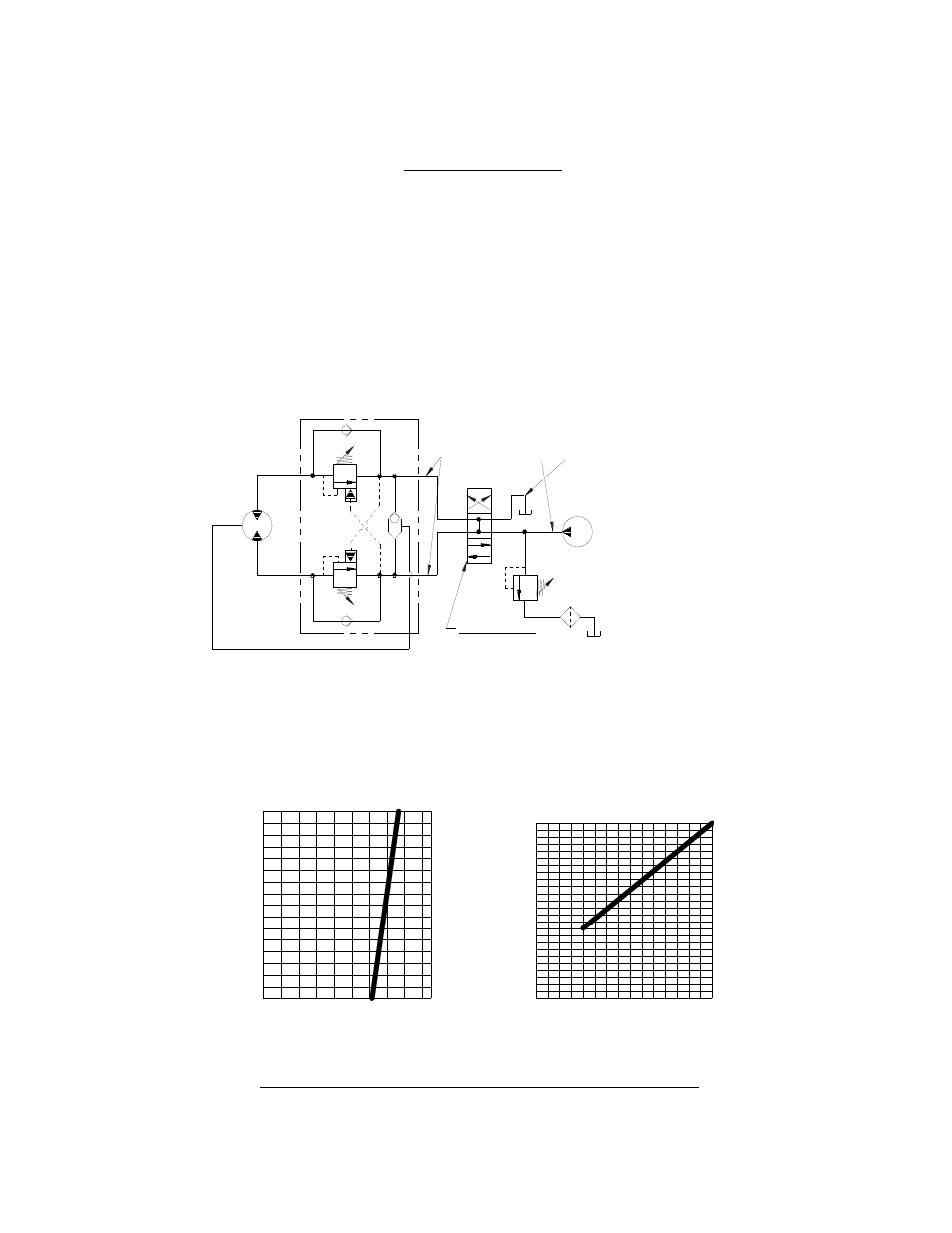
TYPICAL LAYOUT
LOW PRESSURE LINE
(.75 I.D. MINIMUM)
MAX. FLOW &
PRESSURE AT
RATED LOAD:
15 GPM
2300 PSI
PUMP
HYDRAULIC SYSTEM REQUIREMNTS
PERFORMANCE WITH 24.0 CU. IN. HYDRAULIC MOTOR:
LINE PULL
,
L
B
S
FIRST LAYER
FIRST LAYER
LINE SPE
E
D
,
FPM
WORKING PRESSURE, PSI
AT 15 GPM
500
0
0
2300
2000
1000
1500
3000
6000
FLOW, GPM
0
0
15
5
10
5
10
15000
9000
12000
15
20
16000
25
PERFORMANCE CHARTS
Refer to the performance charts below to properly match your hydraulic system to the winch performance. The charts
consist of: (1) line pull (LB) first layer vs. working pressure (PSI); line speed, first layer (FPM) vs. flow (GPM). A
motor spool directional control valve is recommended.
SYSTEM REQUIREMENTS
2300 PSI RELIEF VALVE SETTING
15 GPM FLOW RATE*
10 MICRON NORMAL FILTRATION
Caution: Do not exceed 30 gpm. If exceeded, motor and winch may be damaged.
- ATV 2500 ROCKER SWITCH 256117 (4 pages)
- ATV 2500 ROCKER SWITCH FOR WIRELESS REMOTE 256118 (4 pages)
- ATV REPLACEMENT MINI ROCKER SWITCH 256128 (8 pages)
- ATV REPLACEMENT MINI ROCKER SWITCH FOR WIRELESS 256129 (4 pages)
- ATV SYNTHETIC ROPE KIT 251268 (4 pages)
- ATV SYNTHETIC ROPE KIT, LESS HOOK TAMARACK 251294 (4 pages)
- ATV SYNTHETIC ROPE KIT, TAMARACK 251297 (4 pages)
- ATV WINCH QUICK MOUNT KIT 251076 (4 pages)
- ATV_BADGER 2500 BRAKE 256116 (4 pages)
- ATV UNIVERSAL WIRELESS REMOTE FOR ATV WINCHES (24 pages)
- ATV WIRELESS REMOTE FOR ATV (12 pages)
- ATV WIRELESS REMOTE FOR ATV TAMARACK (12 pages)
- ATV WIRELESS REMOTE FOR BADGER 2500 (6 pages)
- ATV 8 WITH REMOTE (36 pages)
- ATV-2500 (24 pages)
- ATV-2500 (W_Brake) (16 pages)
- ATV-2500 TAMARACK W_MINI ROCKER SWITCH (16 pages)
- ATV-2500 W_MINI ROCKER SWITCH (16 pages)
- ATV-3000 (16 pages)
- ATV-3000 TAMARACK W_SYNTHETIC ROPE (12 pages)
- ATV-3000 W_MINI ROCKER SWITCH (16 pages)
- ATV-3000 W_SYNTHETIC ROPE (12 pages)
- UTV Honcho 5000 (12 pages)
- PATRIOT 12000_15000 SUN GEAR REPLACEMENT KIT 251275 (3 pages)
- PATRIOT 15000 BRAKE REPLACEMENT KIT 251252 (5 pages)
- REP-8000 24V MOTOR REPLACEMENT 251277 (4 pages)
- SAFETY ON_OFF SWITCH KIT 282062, 282063 (20 pages)
- SYNTHETIC ROPE KIT 251262 (8 pages)
- UNIV. WIRELESS REMOTE FOR FR. MOUNT WINCHES 251200-251202 (8 pages)
- BADGER 2500 (8 pages)
- BADGER 2500 W_PENDANT REMOTE (12 pages)
- BADGER 2500 W_WIRELESS REMOTE (10 pages)
- PATRIOT 12000 (12 pages)
- PATRIOT 15000 (12 pages)
- PATRIOT 15000 (42 pages)
- PATRIOT 15000 W_LOWERED SOLENOID (12 pages)
- PATRIOT 6000, 8000 & 9500 (12 pages)
- PATRIOT 6000, 8000 & 9500 (46 pages)
- PATRIOT 9500 UT (12 pages)
- PATRIOT 9500 W_SYNTHETIC ROPE (12 pages)
- PATRIOT PROFILE 12000 (11 pages)
- PATRIOT PROFILE 12000 (50 pages)
- PATRIOT PROFILE 6000, 8000, & 9500 (66 pages)
- PATRIOT PROFILE 9500 UT (12 pages)
- PATRIOT PROFILE-6000_8000_9000_9500 (16 pages)