Badger 2500 wireless remote installation, On /o ff ou t in – Ramsey Winch ATV WIRELESS REMOTE FOR BADGER 2500 User Manual
Page 5
BADGER 2500 WIRELESS REMOTE INSTALLATION
5
8
4. Place directional plate over switch and secure using knurled nut. Using
wrench, tighten backup nut securely against inside of instrument cover.
Make sure directional plate is installed in the same direction as the tog-
gle switch movement.
5. Place rubber boot over switch and tighten securely.
Wiring the Toggle Switch
NOTE: For clarification see wiring schematic on page 4.
1. Connect red wire to center spade.
2. Connect green wire to the toggle switch terminal in the “OUT” position.
3. Connect the yellow wire to the toggle switch terminal in the “IN” posi-
tion.
Connecting the Receiver Power Lead
1. Connect the red wire w/ white stripe to the recommended customer-
supplied switch using the spade connectors. See wiring schematic on
page 4 for recommended switch and wiring specifications.
2. Connect customer-supplied switch to red battery lead.
Installing the Antenna
1. Find an appropriate location and mount magnetic antenna. Make sure-
magnetic base of antenna holds securely to a flat steel or iron surface.
2. Carefully route antenna cable and receiver cable. Be sure to avoid
sharp edges. Connect the receiver and antenna cables.
3. Neatly coil excess cable and secure with cable ties. Stow the coils in a
convenient location where they will not come in contact with any mov-
ing parts or sharp edges.
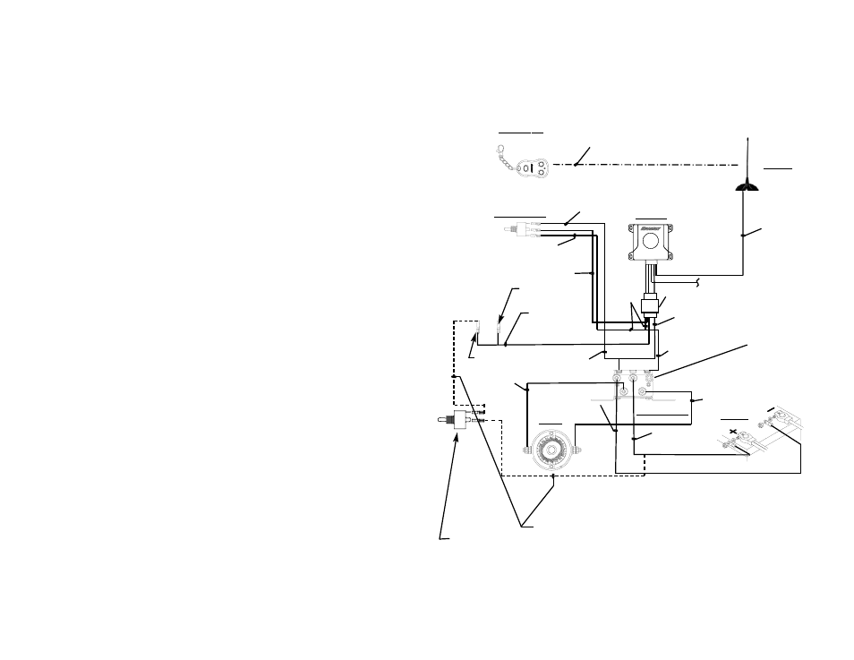
BADGER 2500 WIRELESS REMOTE Electrical Schematic
Programing instructions: Press and hold membrane below,
press ON/OFF button on transmitter for 3 seconds ,
press OUT button for 3 seconds or until winch activation .
WWW.RAMSEY.COM
(918)438-2760 FAX(918)438-6688
Tulsa . Oklahoma, USA
.
.
PUSH
BLACK WIRE
TO GROUND
WIRING
HARNESS
YELLOW WIRE
SOLENOID ASS’Y.
BLACK W/
YELLOW STRIPE
MOTOR LEAD
RED
BATTERY LEAD
BLACK
BATTERY LEAD
#1
MOTOR
BATTERY
#2
YELLOW WIRE
YELLOW
WIRE
GREEN WIRE
GREEN WIRE
BLACK MOTOR
LEAD
GREEN WIRE
WIRELESS
SIGNAL
RED WIRE W/
WHITE STRIPE
RED WIRE
ANTENNA
RECEIVER
TRANSMITTER
TOGGLE SWITCH
COAX CABLE
FEMALE SPADE
CONNECTOR
MALE SPADE
CONNECTOR
NOTE:
TORQUE SOLENOID
TERMINAL NUTS TO
35-40 IN-LBS.
E
A
C
B
CUSTOMER-SUPPLIED
POWER SWITCH
(SPST 5A @ 125V
minimum)
18 ga insulated
wiring per SAE
J1128 GPT or better.
ON
/O
FF
OU
T
IN