Technical specifications – Lincoln Electric IM10171 WIRE FEED MODULE User Manual
Page 9
A-1
INSTALLATION
WIRE FEED MODULE™
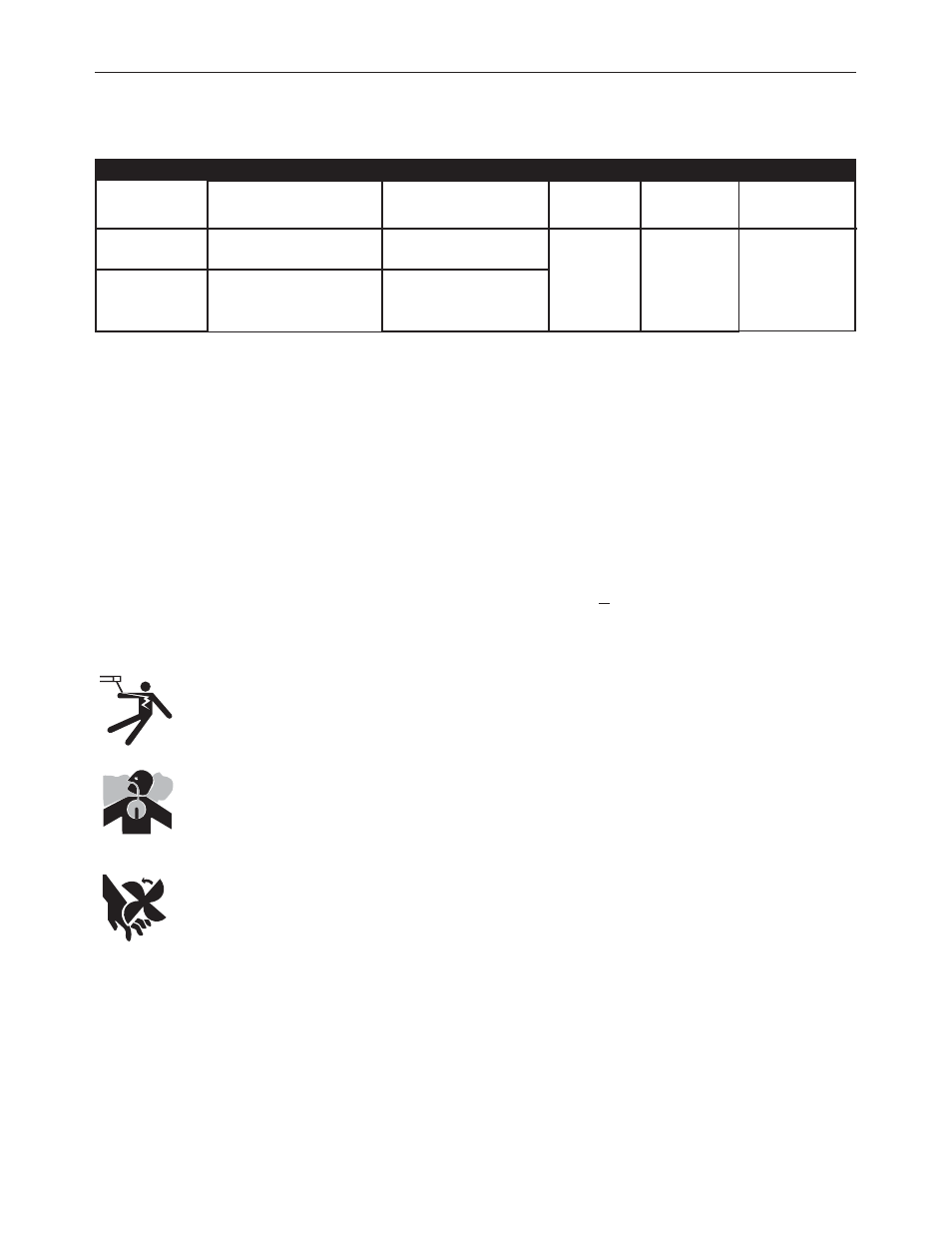
TECHNICAL SPECIFICATIONS
RATED OUTPUT
Model
Classic
®
300HE
SAE-300
®
HE
K3964-1 Wire Feed Module
to be Field Installed
K3198-1
K3201-1
K3202-1
Factory-Installed Wire
Feed Module & Welder Per:
Not Available
K3201-2
Not Available
Rating @ 60%
Duty Cycle
300 Amps
@ 35V
Max. Output @
35% Duty Cycle
325 Amps
@ 34V
Auxiliary Power
Auxiliary Power
is Reduced 25%
in the CV Mode
SAFETY PRECAUTIONS
Do not attempt to use this equipment until you have thor-
oughly read all operating and maintenance manuals supplied
with your machine. They include important safety precau-
tions, detailed engine starting, operating and maintenance
instructions and parts lists.
Have a qualified technician do the maintenance and trou-
bleshooting work. Turn engine off before working inside the
machine. In some cases it may be necessary to remove safety
guards to perform required maintenance. Remove guards
only when necessary and replace them when the mainte-
nance requiring removal is complete. Always use
the greatest care when working near moving parts.
ELECTRIC SHOCK can kill.
• Do not touch electrically live parts such as
output terminals or internal wiring.
ENGINE EXHAUST can kill.
• Use in open, well ventilated areas or vent
exhaust outside.
MOVING PARTS can injure.
• Do not operate with doors open or guards off.
• Stop engine before servicing.
• Keep away from moving parts.
Only qualified personnel should install, use, or service this
equipment.
------------------------------------------------------------------
MACHINE GROUNDING
Because a portable engine driven welder or generator creates its
own power, it is not necessary to connect its frame to an earth
ground, unless the machine is connected to premises wiring (your
home, shop, etc.)
To prevent dangerous electric shock, other equipment to which an
engine driven welder supplies power must:
1. Be grounded to the frame of the welder using a grounded
type plug,
or
2. Be double insulated.
When a welder is mounted on a truck or trailer, its frame must be
securely connected to the metal frame of the vehicle.
Where an engine driven welder is connected to premises wiring
such as that in your home or shop, its frame must be connected
for the system earth ground. See further connection instructions
in the section entitled “Standby Power Connections” as well as the
article on grounding in the latest U.S. National Electrical Code and
the local code.
In general, if the machine is to be grounded, it should be connect-
ed with a #8 or larger copper wire to a solid earth ground such as
a metal water pipe going into the ground for at least 10 feet and
having no insulated joints or to the metal framework of a building
which has been effectively grounded. The U.S. National Electrical
Code lists a number of alternate means of grounding electrical
equipment. A machine grounding stud marked with the symbol
is provided on the Generator Mount of the welder.