Power supply primary power connections – Lincoln Electric 718117 Spirit II 400 User Manual
Page 29
Spirit II User’s Manual
Section 3: Installation
This information is subject to the controls of the Export Administration Regulations [EAR]. This information shall not be provided to
non-U.S. persons or transferred by any means to any location outside the United States contrary to the requirements of the EAR.
3-5
Power Supply Primary Power Connections
** Before connecting primary power, check the data plate
on the power supply to verify the voltage required **
A primary disconnect switch, switching all ungrounded supply conductors, should be
provided for each Spirit system. The disconnect switch should be located as close as
possible to the power supply so it can be turned off quickly in case of an emergency.
The disconnect switch should be equipped with time delay fuses only. The
magnetic inrush current of the power supply will cause fast acting fuses to blow. The
disconnect switch should be sized according to local and national codes. The rating
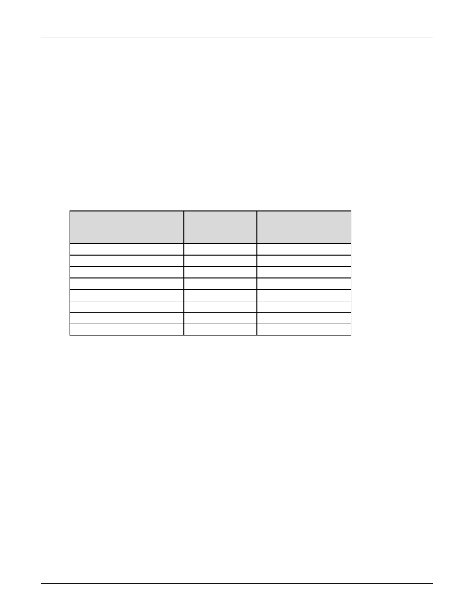
must meet or exceed the continuous rating of the fuses used. See the following chart
for recommended fuse sizes:
3 Phase
Input Voltage (VAC)
Input Current
at Maximum
Output (amps)
Recommended
Time-Delay Fuse
Size (amps)
220 VAC, 60Hz
262
350
240 VAC, 60Hz
240
300
380 VAC, 50/60Hz
152
200
400 VAC, 50/60Hz
144
175
415 VAC, 50/60Hz
140
175
440 VAC, 50/60Hz
131
175
480 VAC, 60Hz
120
150
600 VAC, 60Hz
96
125
Connection to the supply circuit can be by means of flexible supply cables or supply
cables through conduit to a permanent installation. The supply cables should have a
600 volt minimum rating and should be sized according to local and national codes.
Route flexible supply cables through the strain relief on the back of the power supply
and connect to the input terminal block TB5 as shown. For supply cables through
conduit, install the conduit in place of the strain relief and connect the associated supply
cables to the input terminal block TB5. See Figure 3 on the next page.
TB5 is located on the rear of the power supply and is accessible with the right-side
cover removed.
Be sure to connect the primary ground cable to the ground stud
on the input terminal block.
Under no circumstances are the supply cables to be routed through the opening in the
power supply cabinet without conduit or an appropriate strain relief as per local and
national codes.