Operation, Caution – Lincoln Electric IM10122 SAE400 User Manual
Page 14
B-3
OPERATION
B-3
ENGINE TEMPERATURE GAUGE
Displays the coolant temperature in the engine block.
ENGINE OIL PRESSURE GAUGE
Displays the oil pressure to the engine. When the engine
starts running, watch for the oil pressure to build up. If no
pressure shows within 30 seconds, stop the engine and
consult the engine instruction manual.
BATTERY CHARGING AMMETER
Displays the current going from the charging alternator
into the batteries. It is normal for charging current to be
high (above 15 amps) after starting or when the batteries
are ʻlowʼ on charge.
ENGINE HOUR METER
The engine hour meter records the total running time on
the engine in hours. It can be used to keep a record of
maintenance on the engine and or welder.
ENGINE PROTECTION SYSTEM
The engine protection system shuts down the engine
under high coolant temperature or low engine oil pressure
conditions by allowing the fuel solenoid valve to close.
WELDER CONTROLS
POLARITY SWITCH
Turn the Arc Polarity switch to electrode positive or elec-
trode negative as required for each particular application.
CONTROL OF WELDING CURRENT
Purpose of Controls
The continuous “Current Control” is the main current
adjuster. The “Job Selector” is both a fine current adjuster
and the continuous Open Circuit Voltage adjuster. Open
Circuit Voltage (OCV) controls the arc characteristics.
“Job Selector”
The “Job Selector” dial is divided into four colored sec-
tions providing OCV ranges as follows:
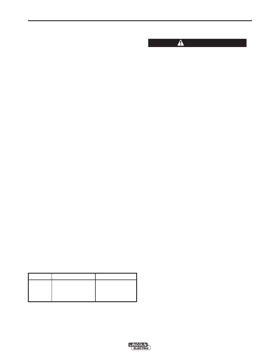
Color
Title
OCV Range
White
Large Electrodes
High OCV
Black
Normal Welding
Medium OCV
Red
Overhead & Vertical
Low OCV
Grey
Special Applications
Extra-Low OCV
The “Job Selector” is usually set in the black range
because it provides a soft “Buttering “ arc desired for most
welding. Some operators prefer to set the “Job Selector”
in the red range for a snappy “Digging” arc when welding
vertical up or overhead.
“CURRENT CONTROL”
Do not adjust the “Current Control” while welding
because this can damage the control.
------------------------------------------------------------------------
The “Current Control” dial is calibrated in amperes on
three separate colored dials corresponding to the
white, black and red ranges of the “Job Selector” dial.
For example: when the “Job Selector” is set on the
black range, the approximate welding current is indi-
cated on the black scale of the “Current Control” dial.
How to Set the Controls
Assume you want a normal soft arc and about 135
amps, using a 5/32” (4.0 mm) electrode:
1. Set the “Job Selector” at the center of the black
range.
2. Set the “Current Control” to read 135 amps on the
black dial.
3. Start to weld.
4. If you want a little more current, turn the “Job
Selector” up (counterclockwise) to increase cur-
rent. If you want a little less current, turn the “Job
Selector” down (clockwise) to decrease current.
5. If dialing the desired current with the “Job
Selector” moves the setting outside the black
range causing undesirable arc characteristics, turn
the “Job Selector” back to the center of the black
range. Then turn the “Current Control” up or down
a little as needed. Readjust the “Job Selector” for
the exact characteristics and current desired.
REMOTE CONTROL
A receptacle and “Local/Remote” control switch is
located on the lower front control panel. A remote con-
trol box with 100 ft. (30.5 m) of cord for adjusting the
OCV at the welding site is available. Putting the switch
in the “REMOTE” position allows fine current control at
the remote control box while placing the switch in the
“LOCAL” position allows fine current control at the “Job
Selector” on the machine. When using the optional
field installed CV adapter (K385-[ ]) the “Local/Remote”
switch is only active in the “VV” mode.
SAE-400
®
CAUTION