Installation, Input connection, Input fuse and supply wire considerations – Lincoln Electric IM10040 POWER WAVE C300 User Manual
Page 14: Input voltage selection, Power cord replacement, Warning
A-4
INSTALLATION
POWER WAVE
®
C300
A-4
INPUT CONNECTION
Only a qualified electrician should
connect the input leads to the
POWER WAVE
®
C300. Connections
should be made in accordance with
all local and national electrical
codes and the connection diagram located on the
inside of the reconnect access door of the
machine. Failure to do so may result in bodily
injury or death.
------------------------------------------------------------------------
A 15 ft. power cord is provided and wired into the
machine. Follow the power cord connection instruc-
tions.
For Single Phase Input
Connect green lead to ground per National Electrical
Code.
Connect black and white leads to power.
Wrap red lead with tape to provide 600V insulation.
For Three Phase Input
Connect green lead to ground per National Electric
Code.
Connect black, red and white leads to power.
INPUT FUSE AND SUPPLY WIRE
CONSIDERATIONS
Refer to Specification Section for recommended fuse,
wire sizes and type of the copper wires. Fuse the
input circuit with the recommended super lag fuse or
delay type breakers (also called "inverse time" or
"thermal/magnetic" circuit breakers). Choose input
and grounding wire size according to local or national
electrical codes. Using input wire sizes, fuses or cir-
cuit breakers smaller than recommended may result in
"nuisance" shut-offs from welder inrush currents, even
if the machine is not being used at high currents.
INPUT VOLTAGE SELECTION
The POWER WAVE
®
C300 automatically adjusts to
work with different input voltages. No reconnect
switches settings are required.
The POWER WAVE
®
C300 ON/OFF
switch is not intended as a service
disconnect for this equipment. Only
a qualified electrician should con-
nect the input leads to the POWER
WAVE
®
C300. Connections should
be made in accordance with all local and national
electrical codes and the connection diagram locat-
ed on the inside of the reconnect access door of
the machine. Failure to do so may result in bodily
injury or death.
------------------------------------------------------------------------
POWER CORD REPLACEMENT
Only a qualified electrician should
connect the input leads to the
POWER WAVE
®
C300. Connections
should be made in accordance with
all local and national electrical
codes and the connection diagram
located on the inside of the reconnect access
door of the machine. Failure to do so may result
in bodily injury or death.
------------------------------------------------------------------------
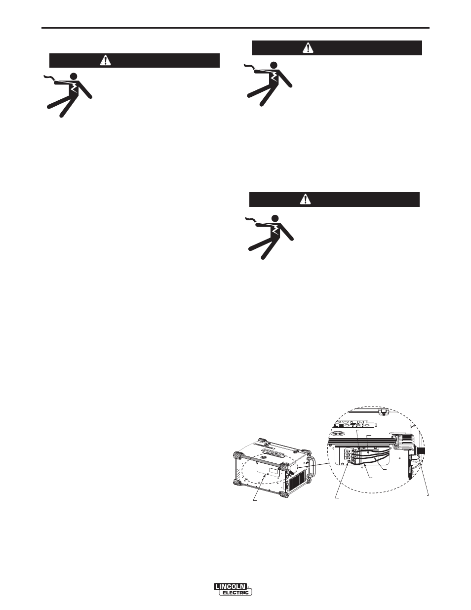
If the input power cord is damaged or needs to be
replaced an input power connection block is located in
the access panel under the wire spool.
ALWAYS CONNECT THE POWERWAVE GROUND-
ING LUG (LOCATED INSIDE THE ACCESS PANEL)
TO A PROPER SAFETY (EARTH) GROUND.
FIGURE A.1
WARNING
WARNING
WARNING
GROUND LUG
BLACK
RED
WHITE
GREEEN
INPUT CORD
ACCESS PANEL