Installation – Lincoln Electric IM10098 CRUISER User Manual
Page 12
A-5
INSTALLATION
CRUISER™
A-5
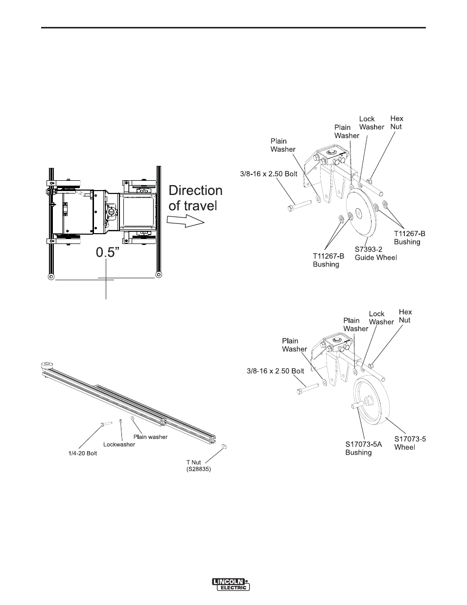
OUTRIGGERS
The outriggers “steer” the
CRUISER™
along a vertical
surface by driving it at a slight angle. Suggested offset
between the front and rear outriggers is ½” (12.7mm).
Larger offsets increase the friction driving the
CRUIS-
ER™
forward and may cause travel motor overcurrent
errors and rapid wheel wear.
When assembling the
CRUISER™
, adjust the cross
slide to the middle position and position the wire in the
joint. Then assemble the front and rear outriggers, and
make fine adjustments to the wire position using the
cross slide.
The outriggers may be stacked to gain extra length.
Slide a T Nut (S28835) into the extrusion and then
insert a ¼-20 bolt through the outrigger slots.
MANUAL STEERING MECHANISM,
ASSEMBLY
As shipped from the factory, the manual steering
mechanism is assembled with a guide wheel for track-
ing in a butt joint. The guide wheel may be replaced
with a rubber wheel for manual steering.
FIGURE A.5 - OUTRIGGERS
FIGURE A.6 - OUTRIGGERS EXTENSION
FIGURE A.7 - MANUAL STEERING MECHANISM
- Invertec V310-T DC (2 pages)
- VANTAGE 500 (CE) 11575 (50 pages)
- INVERTEC V350-PRO SVM152-A (155 pages)
- IMVERTEC V160-T (36 pages)
- IDEALARC CV-300 (112 pages)
- INVERTEC POWER WAVE 450 SVM112-B (293 pages)
- AUTO-DARKENING HELMET IM10001 (12 pages)
- IM10111 IDEALARC R3R-500-I (28 pages)
- IM10110 IDEALARC R3R-400 (25 pages)
- IM10051 INVERTEC V311-T AC_DC (38 pages)
- IM10059 SQUARE WAVE TIG 175 (30 pages)
- IM10096 POWER MIG 256 (37 pages)
- IM10096 POWER MIG 256 (38 pages)
- IM10105 POWER MIG 350MP (47 pages)
- IM10115 FLEXTEC 650 (42 pages)
- IM10132 FLEXTEC 650 (56 pages)
- IM10132 FLEXTEC 650 (36 pages)
- IM10018 IDEALARC DC-600 VRD (55 pages)
- IM10107 IDEALARC DC-400 (40 pages)
- IM10062 FLEXTEC 450 (72 pages)
- IM10091 FLEXTEC 450 CE (40 pages)
- IM10094 RED-D-ARC FX450 (31 pages)
- IM10157 12_24V 10A Auto HF Household Charger (16 pages)
- IM10139 JUMP STARTER (12 pages)
- IM10149 POWER WAVE ADVANCED MODULE (46 pages)
- IM10102 AIR VANTAGE 650 (60 pages)
- IM10103 AIR VANTAGE 700 (AU) (57 pages)
- IM10065 AIR VANTAGE 500 CUMMINS (54 pages)
- IM10066 AIR VANTAGE 500 (AU) (56 pages)
- IM10041 VANTAGE 500 CUMMINS (56 pages)
- IM10128 AIR VANTAGE 500 KUBOTA (AU) (56 pages)
- IM10090 ARC TRACKER (48 pages)
- IM10147 AUTO-DARKENING HELMET (12 pages)
- IM10087 AutoDrive 19 CONTROLLER (28 pages)
- IM10125 AutoDrive 19 TANDEM (34 pages)
- IM10069 AutoDrive 4R100 (32 pages)
- IM10145 AUTOPRO 20 (24 pages)
- IM10025 BIG RED 500 (40 pages)
- IM10019 BIG RED 600 (41 pages)
- IM10005 BULLDOG 140 (46 pages)
- IM10074 BULLDOG 5500 (56 pages)
- IM10067 CENTURY AC120 (20 pages)
- IM10109 CIRCULATOR (33 pages)
- IM10109 CIRCULATOR (36 pages)
- IM10153 CLASSIC 300 HE (60 pages)