Tb-3, Tb-4 – Warner Electric CBC-300C Dual User Manual
Page 8
8
Warner Electric • 800-825-9050
P-269-1
External Potentiometer wiring for
CBC-300 Series Controls
Enclosed Models
CBC-300-1
CBC-300-2
CBC-300-3
Depending on which control is being used,
options for external potentiometer are available
via terminal blocks on the PC board of the unit.
q 1. For CBC-300-2 only, remove the internal
torque adjust knob.
q 2. Remove the four screw that hold the
bracket assembly and PC Board to the
chassis. This step applies to all versions of
the enclosed models.
q 3. Based on which model being used, route
the potentiometer cable(s) through one of the
conduit entrance holes on the bottom of the
unit and wire to the appropriate terminal
block on the PC board. Refer to the wiring
diagrams below for the proper connections.
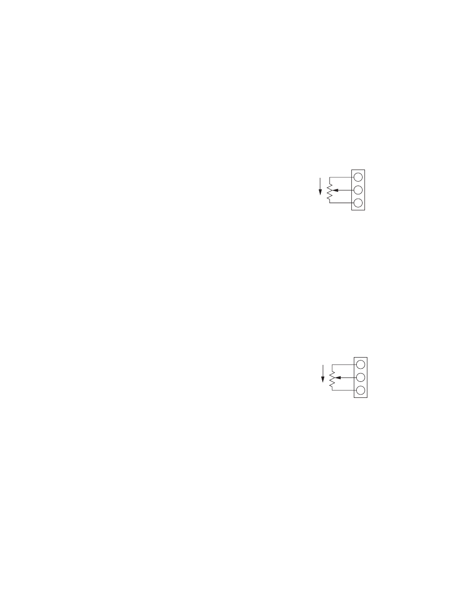
CBC-300-1
External Current Limit Adjustment
q 1. Wire the external current limit
potentiometer to Terminal Block TB-3 for
Channel 1 and TB-4 for Channel 2 as shown
in the diagram. (See Figures 6 & 7)
q 2. If the accessory potentiometer kit is used,
wire the potentiometers per the colors as
shown in the diagram.
q 3. Make sure all terminals are securely
fastened and the wiring cable is secured so
that it can’t pull loose from the terminals.
CBC-300-1, CBC-300-1C
External Current
Limit Adjust
WHT
RED
BLK
CW
10K POT
10 FT MAX
CH1
TB3
3
2
1
TB-3
(Figure 6)
CBC-300-1, CBC-300-1C
External Current
Limit Adjust
WHT
RED
BLK
CW
10K POT
10 FT MAX
10K, 2W POT
10% TOL, LINEAR OR
6011-101-002
ACCESSORY KIT (1)
CH2
TB4
3
2
1
TB-4
(Figure 7)