Warner Electric CBC-300C Dual User Manual
Page 6
6
Warner Electric • 800-825-9050
P-269-1
Electrical Connections
All electrical current must be
off when making electrical connections to
prevent injury or death which can result from
contact with live wires.
AC Input Power Connections
q 1. Connect Earth Ground wire to Terminal 1
and tighten securely.
q 2. Connect the Hot side of the 120 VAC line
to Terminal 2 and tighten securely.
Note: Customer supplied fuse is desirable.
See diagram for connection and sizing.
q 3. Connect the neutral side of the 120 VAC
line to Terminal 3 and tighten securely.
q 4. Determine which clutch/brake arrangement
is to be used and proceed to the appropriate
wiring section.
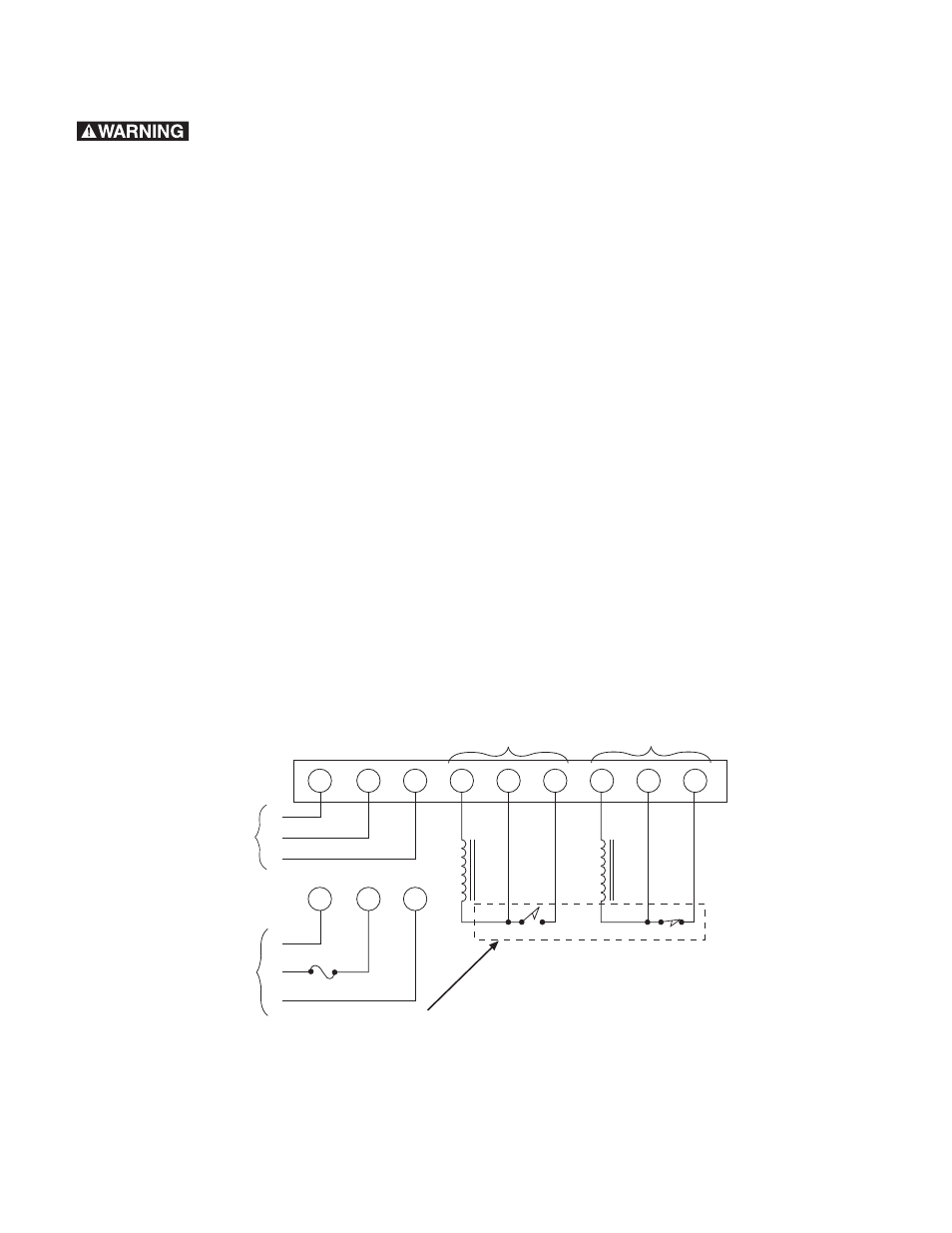
4
5
6
7
8
9
2
3
1
2
3
1
1.5A
FUSE
or
G
H
N
120 VAC
G
H
N
120 VAC
Clutch
Brake
Channel 1
Channel 2
+
-
+
-
Note: CBC-300 Channel 1
and Channel 2 current
output is adjustable.
Note: If Solid-state NPN switching
is used, emitter is connected to
terminal 6 or 9 and collector is
connected to terminal 5 or 8.
External switching by
customer, see
specification.
Normal Clutch–Brake Wiring
(Power applied clutch or brakes)
(Figure 3)
q 1. Connect either the clutch or brake magnet to
Terminals 4 and 5. Tighten Terminal 4 securely.
q 2. Connect the other magnet, either brake or
clutch to Terminals 7 and 8. Tighten Terminal 7
securely.
q 3. Connect switching for Channel 1 to Terminals
5 and 6. Tighten both terminals securely.
q 4. Connect switching for Channel 2 to Terminals
8 and 9. Tighten both terminals securely.
q 5. Set DIP Switch, SW1 for proper current
setting before applying power to the control.
See Internal Switch Settings Chart for proper
DIP Switch settings
q 6. If external potentiometers are being used,
then proceed to the external potentiometer
wiring section. If external potentiometers are not
used, this completes the wiring of the control.
q 7. Double check all connections before applying
power.