WARN PullzAll SERVICE GUIDE 885005 & 885006 User Manual
Page 41
987606A1.doc
Page 41 of 46
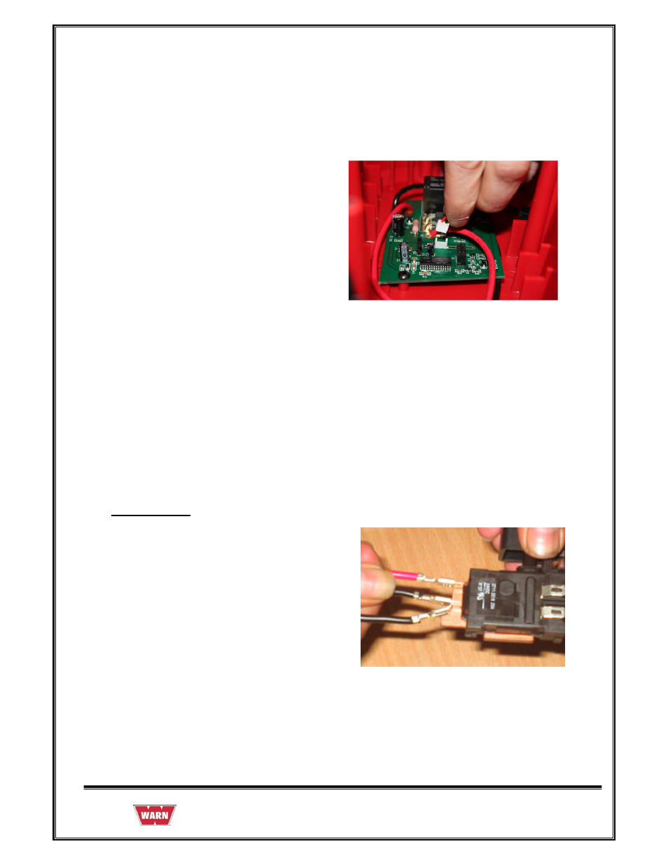
5. Route Red Lead Wire (soldered to Male
Terminal Support) from J2 Terminal on
Circuit Board through wire guides up to
rear of Housing to where the Male
Terminal support is mounted.
Trigger Switch
6. Route Red Lead Wire from load limiter
circuit board J3 and black wire from load
limiter J4 through wire guides up in to
handle to Trigger Switch (Red to B+,
Black to B-) Black wire is connected to
black wire from rocker switch.
See also other documents in the category WARN For the car:
- ZEON 8-S (36 pages)
- ZEON 8-S Synthetic Rope (50 pages)
- ZEON 10-S Multi-Mount (12 pages)
- ZEON 10-S Multi-Mount (6 pages)
- OLYMPUS 25 S-9X12-M-BLK (2 pages)
- OLYMPUS 25 S-9X12-M-POL (2 pages)
- 15-S Series Spydura Pro (2 pages)
- 15-S Series Spydura ProMax (2 pages)
- S-12 Series Spydura Pro (2 pages)
- S-12 Series Spydura ProMax (2 pages)
- S-9 Series Spydura Pro (2 pages)
- S-9 Series Spydura ProMax (2 pages)
- Severe Duty 9L 63123 (2 pages)
- Severe Duty 9L 88540 (2 pages)
- Severe Duty 12 (2 pages)
- Severe Duty 18 (2 pages)
- OLYMPUS 22 22W-8X8-A-CRC (2 pages)
- PullzAll Installation (32 pages)
- PullzAll BATTERY CHARGER (36 pages)
- PullzAll SERVICE GUIDE 685005, 685006 & 685007 (45 pages)
- Vantage 2000 (36 pages)
- M12000 (20 pages)
- 16.5ti (20 pages)
- 20XL-LP Series (16 pages)
- 30XL-LP 81617 (2 pages)
- 30XL 82710 (2 pages)
- 9 DC Series 12V (2 pages)
- 9 DC Series 24V (2 pages)
- 12 DC Series 12V (2 pages)
- 12 DC Series 24V (2 pages)
- 15 DC Series 12V (2 pages)
- 15 DC Series 24V (2 pages)
- 18 DC Series (2 pages)
- 6 Series Hydraulic (Anti-clockwise) (2 pages)
- 9 Series Hydraulic (Anti-clockwise, 4.9 cu in motor) (2 pages)
- 9 Series Hydraulic (Clockwise, 4.9 cu in motor) (2 pages)
- 9 Series Hydraulic (3.0 cu in motor) (2 pages)
- 9 Series Hydraulic Round Top (2 pages)
- 12 Series Hydraulic (Anti-clockwise) (2 pages)
- 12 Series Hydraulic Round Top (2 pages)
- 15 Series Hydraulic (2 pages)
- 18 Series Hydraulic (2 pages)
- WG9 WINCH (Standard Drum) (2 pages)
- WG9 WINCH (Long Drum) with manual clutch (2 pages)