Know your winch, Mounting – WARN ZEON 12 User Manual
Page 4
WARN INDUSTRIES
7 83449A0
KNOW YOUR WINCH
Know Your Winch
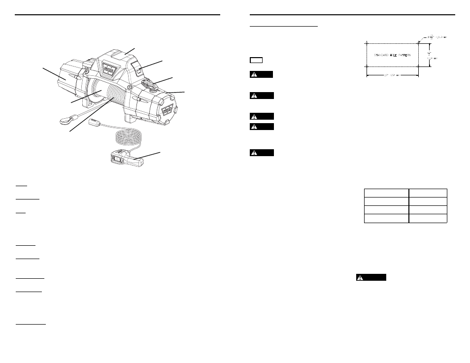
Before you begin, you should familiarize yourself with your WARN winch and each of its components:
Motor:
The winch motor is powered by the vehicle’s battery. The motor provides power to the gear
mechanism, which turns the winch drum and winds the winch rope.
Winch Drum:
The winch drum is the cylinder onto which the winch rope feeds. The drum is driven by the
motor and drive train. Its direction can be changed using the remote control.
Rope*:
The winch rope’s diameter and length are determined by the winch’s load capacity and
design. Wrapped around the winch drum and fed through the fairlead, the winch rope is
looped at the end to accept the hook’s clevis pin.
* For synthetic rope models, be sure to fully read the WARN Synthetic Rope Installation
Instruction manual, included in kit.
Gear Train:
The reduction gear converts the winch motor power into a large pulling force. The gear train
design makes it possible for the winch to be lighter and more compact.
Clutch Lever:
The clutch allows the operator to manually disengage the spooling drum from the gear train,
enabling the drum to rotate freely (known as “freespooling”). Engaging the clutch “locks” the
winch drum back onto the gear train.
Remote Socket:
The remote socket is where the operator plugs in the wired remote control or optional
wireless remote receiver, in order to control the winch.
Control Pack*:
Using electrical power from the vehicle’s battery, the control pack’s contactor switches
power to the motor, enabling the operator to change the direction of the winch drum
rotation.
*For specific applications, the optional Control Pack Relocation Kit details can be found at
your WARN Authorized Dealer or www.warn.com.
Remote Control:
The remote control plugs into the winch control pack, via the remote socket, allowing the
operator to control the winch direction, as well as stand well clear of the wire rope while
operating the winch.
Motor
Control Pack
Remote Socket
Clutch Lever
Transmission
(Gear Train)
Rope
Winch Drum
Remote Control
Figure 1
WARN INDUSTRIES
83449A0 8
MOUNTING
Mounting Bolt Pattern:
Standard: 254 mm x 114.3 mm (10”x 4.5”)
Smooth and fl at mounting surface, minimum
thickness = 6.4 mm (1/4”)
Included Hardware:
• M10x1.5
fl anged locknut 15mm hex
•
M10-1.5 x 35 hex fl ange, 8.8, bolt (4x)
•
M10-1.5 x 40 hex fl ange, 8.8, bolt (2x)
Torque: 41 to 47 Nm (30-35 ft. lbs.)
Choose a mounting location that is sufficiently
strong enough to withstand the maximum pulling
capacity of your winch.
1. Set flanged nuts into pockets of winch feet.
2. Set winch in mounting location. Confirm
required bolt length.
Plate Thickness
Bolt Length
7 mm (1/4”)
32 mm
10 mm (3/8”)
40 mm
13 mm (1/2”)
40 mm
3. Install bolts and tighten to 41 to 47 Nm (30-35
ft. lbs.)
4. Cut elastic band retaining rope.
5. Put clutch into free spool position.
6. Manually feed rope loop through fairlead.
WARNING
Always use supplied hook strap.
7. Attach hook to cable loop. Attach hook strap to
hook.
8. Rotate clutch back into fully engaged position.
Step 1 - Mount the Winch
Winch mounting kits are available from your
WARN Dealer to satisfy nearly all applications. For
information on available kits, contact your WARN
product dealer.
NOTICE For optimal performance and the results you expect,
WARN mounting plates are strongly recommended.
CAUTION
To prevent accidental activation of the winch
and serious injury, complete the winch installation and attach
the hook before installing the wiring.
WARNING
Always choose a mounting location that is
suffi
ciently strong enough to withstand the maximum pulling
capacity of your winch.
WARNING
Never use bolts that are too long.
WARNING
Always spool the winch rope onto the drum
in the direction specifi ed by the drum rotation labels on the
winch and/or in the documentation. This is required for the
automatic brake (if so equipped) to function properly.
WARNING
Always wind the winch rope on the bottom
(mount side) of the drum.
This winch should always be mounted in a
horizontal orientation with the rope winding on/
off the drum on the mount side of the drum and
following the drum rotation arrow as labeled on the
winch, see Figures 2 and 3.
Correct rotation is required for the automatic
brake to function properly. Horizontal mounting
helps prevent the rope from piling up on one end of
the drum which can damage the winch.
The use of recommended bolt and lock washer
combinations torqued to recommended levels will
prevent vibration during operation. Specifications
listed below. Mounting system will dictate bolt
length.