Ssembly, Nstructions, Diagram 1: attach leg weldments to yoke – Vestil AHA User Manual
Page 17
Copyright 2011 Vestil Manufacturing Corp.
Page 17 of 25
A
SSEMBLY
I
NSTRUCTIONS
:
If the crane is improperly assembled, it might malfunction and result in serious personal injuries.
Read this instruction manual in its entirety before assembling the crane; only assemble the crane if you fully
understand both the associated risks and the manufacturer-approved assembly procedure discussed below.
Failure to apply the assembly procedure described in Steps 1-8 below constitutes misuse of the product.
ONLY qualified personnel should assemble the crane.
DO NOT modify the crane in any way
UUU
unless and until
UUU
you receive written approval from Vestil.
DO NOT use the crane if you notice damage to or deformation of the beam, teletubes, or any component of either
of the leg assemblies. Using the crane despite weakness of a structural component could result in crane collapse.
DO NOT use the crane if any of the hardware (bolts, nuts, clamps, etc.) is damaged; you could sustain serious
injuries if the crane collapses. Contact Vestil to order replacement parts.
DO NOT use the crane if any of the casters is damaged. A damaged caster may cause the crane to tip over, and
the possibility that the crane will tip increases while it is used to hoist or support a load.
Modifying the crane in any way automatically voids the limited warranty.
This crane can be used outdoors. However, it should be sheltered from the weather when not in use.
Inspect the crane for damage before each use.
UUU
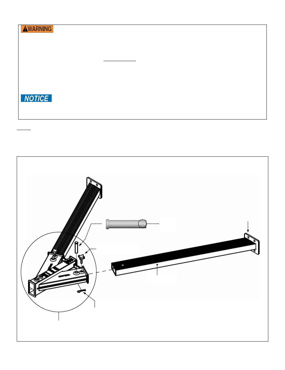
Step 1
UUU
: [2,000 lb. AHA-2-#-# and 4,000 lb. AHA-4-#-# models only] Attach the leg weldments and yokes
Insert the end of each leg weldment into one of the leg openings of the yoke (circled) as shown below. Fasten the leg
weldments to the yoke with clevis pins (AHA-2 models part no. 28-112-031; AHA-4 models part no. 33-112-034), and then
secure the clevis pins by feeding a hitch pin through the hitch pin opening (in the clevis pin). Stabilize the leg weldments in
the yoke by winding a knob through yoke until the end of the knob presses firmly against the leg.
¾ in. diameter clevis pin
(28-112-031 or 33-112-034)
Leg weldment
Yoke
3
/
8
in. - 16 x 1¼ in. knob
Caster mount bracket
Hitch pin
Hitch pin
opening
Diagram 1: Attach leg weldments to yoke