Installation instructions 3xtend/einc l/24, 3 installation - fixing, Mount unit – TREND 3xtend_EINC L_24 User Manual
Page 3: Ab c, Route cables, Ca b
3
3xtend/EINC L/24 Installation Instructions TG200811 Issue 3 Issue 3 3/9/08
Installation Instructions
3xtend/EINC L/24
1.3
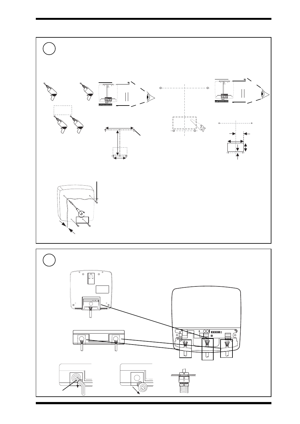
INSTALLATION - FIXING
(Continued)
Mount Unit
(Continued)
4
Or via 4 screw fixing (e.g. fixing on a panel)
a
b
c
4 x M4 x 16 mm
10 mm
Max
126 mm (4.96”)
75 mm
(2.95”)
196 mm
(3.78”)
80 mm (3.15”)
40 mm
(1.57”)
40 mm (1.57”)
8 mm
(0.31”)
Cut rear cable entry hole
if required
1
LERN/24 Installation Instructions TGxxxxxx Issue 1/A dd/mm/yy
Installation Instructions - Template
LERN/24
XXXXXXXXXXXXXXXX
LERN/24
Installation Instructions - Template
Trend Control Systems Ltd reserves the right to revise this publication from time to time and make changes to the content hereof without
obligation to notify any person of such revisions or changes.
Website www.trend-controls.com
Telephone +44 (0)1403 211 888
P.O. Box 34, Horsham, West Sussex, RH12 2YF United Kingdom
Fax (International) +44 (0)1403 210982
E-mail [email protected]
Registered office. Novar House 24 Queens Road Weybridge Surrey KT13 9UX Registered in England No 1664519
Fax (UK) +44 (0)1403 241 608
NOTE: Print to size.
Check dimensions below
10 cm
4"
A
3 hole fixing
Screw size 4 off M4 x 16
Hole/drill 5mm
or alternatively
B
3 hole fixing
(Do not use template for 3 hole fixing, see LERN../SM installation instructions, TGxxxxxx sheet 1 step x.)
A
A
A
A
B
B
B
8 mm (0.31”)
170 mm (6.69”)
196 mm (3.78”)
126 mm (4.96”)
75 mm (2.95”)
80 mm (3.15”)
40 mm (1.57”)
40 mm (1.57”)
20 mm
(0.78”)
37.5 mm (1.48”)
rear cable entry cutout
3xtend/EINC L/24 Template TG200813
4 holes Ø 5 mm
5
Route Cables
1 2 3 4 5 6 7 8 9 10
Rear entry
Fit M20 (¾”) cable
glands
Bottom entry
c
a
b
8 mm Allen key