Installation instructions 3xtend/einc l/24 – TREND 3xtend_EINC L_24 User Manual
Page 11
11
3xtend/EINC L/24 Installation Instructions TG200811 Issue 3 Issue 3 3/9/08
Installation Instructions
3xtend/EINC L/24
Configure Addressing Details with IP Tool
(Continued)
13
1.4
INSTALLATION - CONFIGURATION
(Continued)
Parameter
Description
When to change
Remote
EINC
Modules
IP Address
(read/write) The IP address/host name of the remote device on Ethernet.
The host name or IP address of the remote device on Ethernet.
Range = 0.0.0.0 to 255.255.255.255. Default=0.0.0.0
If i nternetwork is to be bui lt
across routers.
Subnet mask
(read/write) The subnet mask for the remote device.Range = 0.0.0.0 to
255.255.255.255 Default=0.0.0.0
At least two devices from each each subnet should be specifed. For increased reliability details of additional devices
should be specified. If automatic addressing is being used the devices must be specified using hostnames, and if manual
addressing is being used the list should contain the devices with the lowest IP addresses. The table must be placed in
all devices on the network.
Virtual
CNC
Modules
Alarm IP
Address
The host name or IP address of the alarm target supervisor that is
connected to the Ethernet network if operating in alarm mode. Setting
this up switches the virtual CNC into alarm mode, and prevents the virtual
CNC being used as a CNC by a supervisor. 0 will switch the virtual CNC
back into supervisor mode. Default=Unused
If the virtual CNC is to be used
to send alarms to a supervisor
over Ethernet.
CNC Address
The device address of the virtual CNC on EINC L’s Lan. It is set to
unused by default, and the virtual CNC will not operate until its address
i s set up. It can be set to any valid address (1 to 119 excluding
addresses 2, 3, and 10). 0 will disable the virtual CNC.
If the virtual CNC is to be used.
Port Address
The TCP port used by the virtual CNC. It is set unused by default and
then defaults to 10000 plus the cnc address when the cnc address is
set up, but can subsequently be changed.Range = 1 to 32767.
If the virtual CNC is to be used.
14
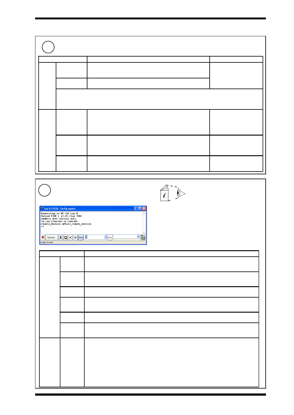
a
Enter configuration mode using SET. The top level
prompt will be displayed as below.
b
Configure the optional settings the relevant upper
case letter and pressing ENTER. If a value has been
changed X+ENTER will confirm it and return to the
top menu, whereas Q+ENTER will quit and return
with the value unchanged. The table below describes
the settings.
SET Manual TE200147
Configure Optional Settings Using SET
Note that it may be necessary to set up a virtual CNC in the
3xtend/EINC L if one is not available elsewhere on the network.
3xtend/EINC L Data Sheet TA200800
Parameter
Description
Address
Module
Lan Alarm
Address
The alarm target device address for alarms generated by the current loop network when it is operating
as a Lan. It can be set to any valid address (1 to 119 excluding addresses 2, 3, and 10). 0 stops the
alarms being transmitted.
Lan Alarm
Lan
The target Lan number for alarms generated by the current loop network when it is operating as a Lan.
It can be set to any valid address (1 to 119 excluding addresses 2, 3, and 10). 0 stops the alarms being
transmitted.
Alarm
Language
The language used for the network alarms. 0=English, 1=Spanish, 2=Finnish, 3=Swedish, 4=Norwegian,
5=Danish, 6=German, 7=Italian, 8=Portuguese, 9=French.
Internetwork
Alarm
Address
The alarm target device address for internetwork alarms. It can be set to any valid address (1 to 119
excluding addresses 2, 3, and 10). 0 stops the alarms being transmitted.
Internetwork
Alarm Lan
The alarm target Lan number for internetwork alarms. It can be set to any valid address (1 to 119 excluding
addresses 2, 3, and 10). 0 stops the alarms being transmitted.
Disable
vCNC Alive
Alarms
Enables/disables device on-line, and device dead alarms generated by virtual CNCs. Range=Yes or No,
Yes = alarms disabled. Default = No.
Remote
Devices
Send
Remote
Broadcasts
Specifies whether remote broadcast messages or directed messages are used to build the internetwork
across routers.
If set to use broadcast messages (Yes) the messages used to build the internetwork across routers
will be sent to the default router requesting a broadcast message to all devices on the remote
device’s subnet as well as the remote device specified in the module.
If set not to use broadcast messages (No) the messages used to build the internetwork across routers
will only be sent (by direct messaging) to the device specified in the module.
This option should only be turned off if the routers have remote broadcast messaging disabled.
If broadcasting is turned off, details of as many device’s as possible from each subnet should be entered
in the remote devices table to enable the internetwork to be built in the event of a failure.