Panel layout of eds-308 series – TREND EDS-305 User Manual
Page 6
—
3 —
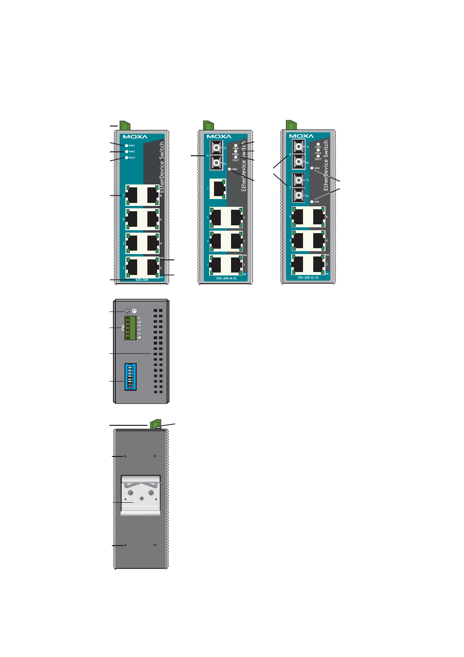
Panel Layout of EDS-308 Series
EDS-308
Front Panel View
5
6
7
8
9
10
11
2
EDS-308-SS-SC
Front Panel View
12
EDS-308-M-SC
Front Panel View
12
13
5
6
7
13
V1 V2 INPUTS: 24 VDC
PWR2
V2+
V2-
V1-
V1+
FAULT
PWR1
123
4
56
78
ON DIP
PORT ALARM
Top Panel View
1
2
3
4
Rear Panel View
1
2
15
14
14
NOTE: The appearance of EDS-308-S-SC is identical to
EDS-308-M-SC, and the appearance of EDS-308-MM-SC is
identical to EDS-308-SS-SC.
1. Grounding
screw
2. Terminal block for power input P1/P2 and relay output
3. Heat dissipation orifices
4. DIP
switches
5. Power input P1 LED
6. Power input P2 LED
7. Fault
LED
8. 10/100BaseT(X)
Port
9. TP port’s 100 Mbps LED
10. TP port’s 10 Mbps LED
11. Model Name
12. 100BaseFX
Port
13. FX port’s 100 Mbps LED
14. Screw hole for wall mounting kit
15. DIN-Rail Kit