Iq246, Iq246 installation instructions – TREND IQ246 User Manual
Page 4
4
IQ246 Controller Installation Instructions TG200101 Issue 1/E 15/01/07
IQ246
Installation Instructions
9
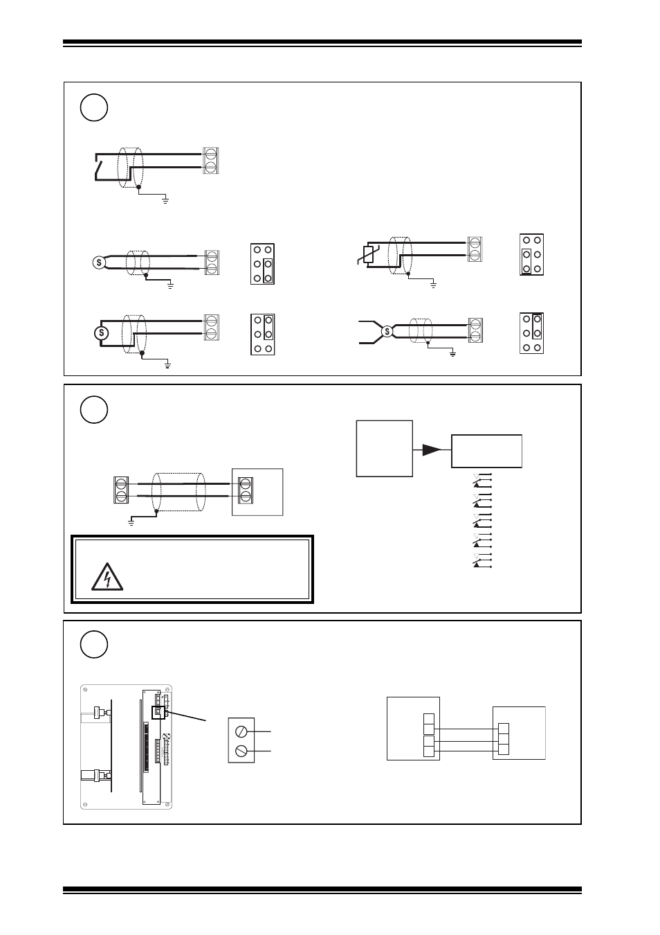
Connect Auxiliary Output Supply
R+
R-
T+
T-
24
V
d
c
0 V
AUX
24
V
d
c
0 V
POW
E
R
24 Vdc Auxiliary Output Supply
0 V
24 V
0 V
24 Vdc
Imax = 500 mA
For relays, NDP
e.g.
SRMV =
2SRM =
2RM =
3RM =
6RM =
x 1
x 2
x 2
x 3
x 6
Relay
Module
IQ246
nRM
7
Connect Inputs
V
1
T
1
Digital inputs
(digital inputs 1 to 32)
Voltage input
Current input (loop powered)
Thermistor input
Current input (external powered)
Dig'n'
+24 V DIG (24Vdc)
Analogue inputs
(analogue inputs 1 to 20)
An'n'
0 V
V (0 to 10V)
SIG
➞ I (0 to 20 mA)
An'n'
24 V
An'n'
0 V
0V
SIG
0V
➞ I (0 to 20 mA)
8
Connect Outputs
(analog outputs 1 to 20)
Additional Relay Modules
WARNING:
The wires may be connected to
hazardous voltages. Disconnect
power before attempting any wiring.
(R/L, H/L)
(HCM/TRM)
An'n'
0 V
0V
Bn
Load
2 4 V
O p ' n '
0 V
I Q 2 4 6
2 4 V
I N
0 V
2 R M
0 V
Trend TP/1/1/22/HF/200 (Belden 8761) cable
recommended for all inputs
Trend TP/1/1/22/HF/200 (Belden 8761) cable
recommended for voltage outputs
3.1 Installation - Mounting
(continued)
(if required)