Iq246 installation instructions, Connecting network, 1 installation - mounting – TREND IQ246 User Manual
Page 2: Mounting, Connecting power, R+ r- t+ t, R+ r- t+ t- 24 vdc 0 v, 24 vdc 0 v
2
IQ246 Controller Installation Instructions TG200101 Issue 1/E 15/01/07
IQ246
Installation Instructions
5
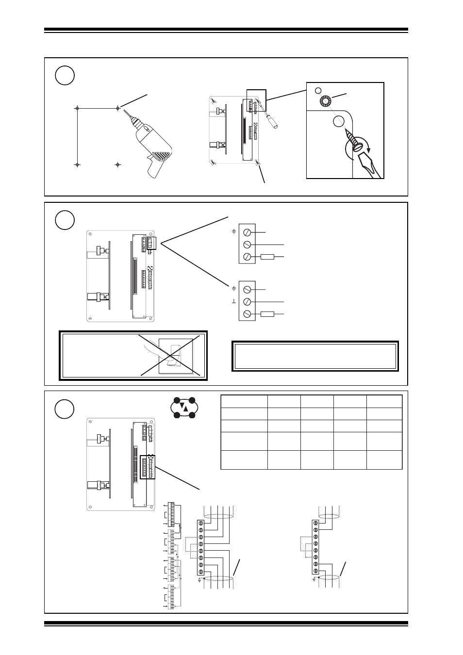
Connecting Network
R+
R-
T+
T-
24
V
d
c
0 V
AUX
24
V
d
c
0 V
POW
E
R
R+
R-
T+
T-
R+
R-
T+
T-
R R
T T
R+
R-
T+
T-
R+
R-
T+
T-
R R
T T R R
T T
4 wire method
Connect to T &
R of previous
device, polarity
independent
terminate
screen at one
end of cable
Connect to T & R of
next device, polarity
independent
Connect to T+,
T- of previous
device, polarity
independent
terminate screen
at transmit end
Connect to R+, R- of
next device, polarity
independent
2 wire method
For more cable and connection information details refer to Network
Engineering Manual 92-1735
R
T
R
T
R
T
R
T
R
T
R
T
R
T
R
T
3.1 Installation - Mounting
(continued)
3
Mounting
R+
R-
T+
T-
24
Vdc
0 V
AUX
24
Vdc
0 V
POW
E
R
∅
6 mm (0.24”)
4
Connecting Power
R+
R-
T+
T-
24
V
d
c
0 V
AUX
24
V
d
c
0 V
POW
E
R
~
24 Vdc - 1.7 A (max)
Earth (ground)
0 V
24 V
Earth (ground)
fuse
fuse
0 V - - - - - - - -Earth, ground (recommended)
24 Vdc
24 Vac
may supply several
controllers
isolated transformer winding,
supply 1 controller only
24 Vac - 72 VA transformer
DO NOT APPLY
POWER
WARNING: This apparatus must be earthed
(grounded) using power connector.
O
1
4 off
washers
4 holes
a
b
}
}
190 mm (7.48”)
135 mm
(5.31”)
e
l
b
a
C
d
u
a
b
2
k
1
d
u
a
b
6
k
9
d
u
a
b
2
k
9
1
s
e
r
i
W
f
o
.
o
N
2
8
1
9
n
e
d
l
e
B
m
0
0
0
1
)
s
d
y
0
9
0
1
(
m
0
0
0
1
)
s
d
y
0
9
0
1
(
m
0
0
7
)
s
d
y
5
6
7
(
2
7
0
2
9
n
e
d
l
e
B
m
0
0
0
1
)
s
d
y
0
9
0
1
(
m
0
0
0
1
)
s
d
y
0
9
0
1
(
m
0
0
5
)
s
d
y
5
4
5
(
2
d
n
e
r
T
0
0
2
/
F
H
/
2
2
/
1
/
1
/
P
T
)
1
6
7
8
n
e
d
l
e
B
(
m
0
0
0
1
)
s
d
y
0
9
0
1
(
m
0
0
7
)
s
d
y
5
6
7
(
m
0
5
3
)
s
d
y
0
8
3
(
2
d
n
e
r
T
0
0
2
/
F
H
/
2
2
/
2
/
2
/
P
T
)
3
2
7
8
n
e
d
l
e
B
(
m
0
0
0
1
)
s
d
y
0
9
0
1
(
m
0
0
5
)
s
d
y
5
4
5
(
m
0
5
2
)
s
d
y
0
7
2
(
4