Iq22x installation instructions - mounting, 3 installation - mounting, Connect relay outputs – TREND IQ22x User Manual
Page 4: Connect auxiliary supply 24 v, Close flap, Close mbox, Configure/ commission
1 - 4
IQ22x Series Contollers Installation Instructions TG200001 Issue 1/G 08/05/06
IQ22x
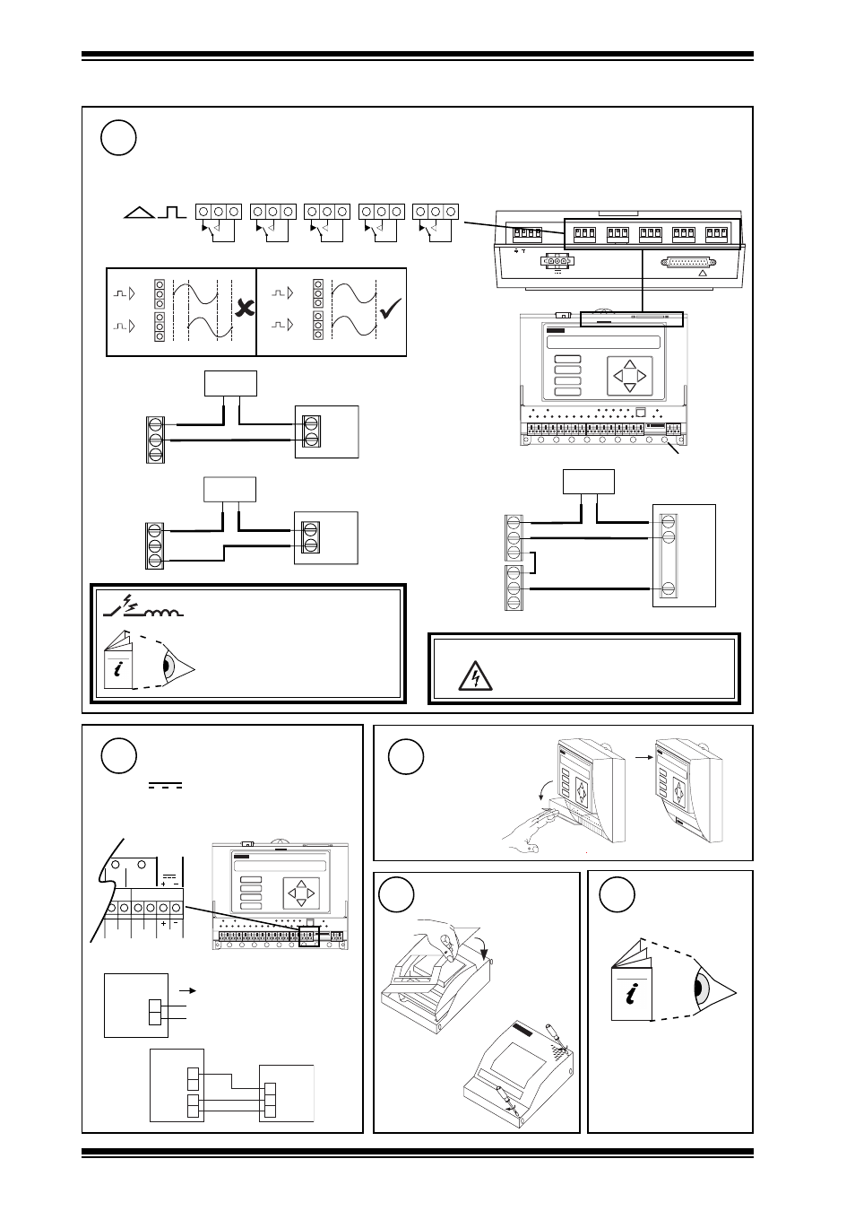
Installation Instructions - Mounting
Connect Relay Outputs
9
WARNING:
The wires may be connected to
hazardous voltages. Disconnect power
before attempting any wiring.
1
2
3
4
5
6
7
8
9
1 0
A
B
C
D
earth (ground) bus
NC
NO
C
power
actuator
n
NC
NO
C
n+1
raise
lower
C
R
L
common
link
2 outputs -
raise/lower
~
2 3 0 V
N C N O C
N C N O C
N C N O C
N C N O C
N C N O C
R D S / R S 2 3 2
!
2 4 V
~
M O D E M
NC NO C
16
NC NO C
17
NC NO C
18
NC NO C
19
NC NO C
20
n+1
n
Æ
a
Æ
b
n+1
n
Æ
a
Æ
a
NC
NO
C
load
n
power
Driver on,
load on
NC
NO
C
load
n
power
Driver off,
load on
Arc suppression
r e c o m m e n d e d
Relay Output Arc Suppression
Installation Instructions TG200208
Terminal size 0.5 to 2.5 mm
2
(14 to 20 AWG)
240 Vac single phase 8 A (resistive) 5 A (inductive, Cos
ø = 0.4)
30 Vdc at 5 A (resistive), 20 Vdc at 5 A (inductive)
24 Vdc (inductive) 2 A
For IQ22x/USA, UL rating applies up to 30 V
1.3 Installation - Mounting
(continued)
AUX
OP6
C
OP7
C
14
15
24V
24V
+
-
IQ22x
C
O P n
I Q 2 2 x
2 4 V
I N
0 V
2 R M
+
2 4 V -
Connect Auxiliary Supply
24 V
10
Close Flap
11
Close MBOX
12
Imax = 100 mA
e.g.
IQ22x Installation Instructions
- Sheet 2: Configuration
1
2
3
4
5
6
7
8
9
1 0
A
B
C
D
Configure/
Commission
13
if fitted in
ENCLS/MBOX /
IQ22x
2
b
a
Terminal size 0.5 to 2.5 mm
2
(14 to 20 AWG)
External channels 16 to 20, configuration channels OP8 to IP12