Rd-iql installation instructions, Installation, Engineer temperature offset – TREND RD-IQL User Manual
Page 4: Check start up reset, Connect to iql+ controller, Continued), Firmware version, Every 7 s: communications failure default=0
RD-IQL
Installation Instructions
RD-IQL Installation Instructions TG200576 Issue 1/G 16/01/07
4
2 4 V a c
I Q
L
+
O / S
L A N
L O N
N I D
S t r a t e g y
: : : : :
D O 1
I N 1
D O 2
D O 3
~
D O 4
D O 5
I N 2
I N 3
2 4 V
C O M
2 4 V
C O M
~
C O M
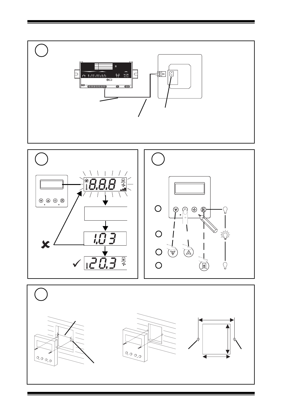
INSTALLATION
(continued)
S P
E N G
1
2
3
4
° C
° F
A U T O
Engineer Temperature Offset
10
S P
E N G
1
2
3
4
if required to offset sensor value
a
b
c
d
or
ENG + 2
Check Start Up Reset
9
Firmware version
° C
A U T O
every 7 s:
communications
failure
default=0
Connect to IQL+ Controller
8
Digital (TBus) input
polarity independent
RD-IQL (rear view)
Note that IQL+/IQLVAV may be connected while powered; if not power up IQL+/IQLVAV.
maximum distance 30m (33 yds)
First digital input:
IN3 for IQL11+,
IN4 for IQL13+ and IQL15+
IN5 for IQLVAV
Mount Unit
11
standard UK electric back box
or panel
60 mm
46 mm
50 mm
M3.5
screw
M3.5
screw
60 mm
2 off
M3.5 x 35 mm screws provided