TREND RD-IQL User Manual
Page 2
RD-IQL
Installation Instructions
RD-IQL Installation Instructions TG200576 Issue 1/G 16/01/07
2
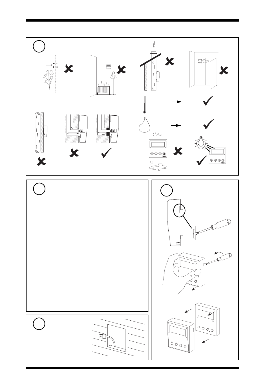
INSTALLATION
(continued)
Requirements
(continued)
2
i
j
k
H O
2
-10 °C
+14 °F
+40 °C
+122 ° F
0 %RH
90 %RH
h
e
d
f
g
l
Remove Front Panel
4
Route Cable
5
b
a
c
Check IQL+, IQLVAV Controller
Compatibility
3
Compatible with IQLVAV, IQL11+, 13+, 15+ only
IQLs must have standard strategies or standard item
allocations as follows:
S9, S10, S1, S2, S3 (IQLVAV, IQL11+, 13+, 15+)
I9 (IQL11+, 13+, 15+), I12 (IQLVAV)
S11, S7 (IQL13+, 15+)
IQLVAV, IQL11+ can use RD/IQL/K, /KOS
IQL13+, 15+ can use RD/IQL/K, /KOS, /KOSF
The RD’s potentiometer must be used (if potentiometer
required); a direct connected potentiometer may not be
used. A direct connected temperature sensor may be
used rather than the RD’s.
RD-IQL/K precludes use of PIR/pushbutton inputs and
(on IQLVAV only) alarm contact input. A separate fan
speed switch may be used (IQL13+, 15+).
RD-IQL/KOS as RD-IQL/K except pushbutton is provided.
RD-IQL/KOSF as RD-IQL/KOS except Fan speed switch
is provided (for IQL13+, 15+). A separate Fan Speed
switch may be used (rather than the RD’s).