Tdqs/tdqh, dq to dqs setup/hold time, Figure 62 – tdqs/tdqh results – Teledyne LeCroy QPHY-DDR4 User Manual
Page 68
Tdqs/Tdqh, DQ to DQS Setup/Hold Time
The purpose of this test is to characterize the setup and hold time between DQ and DQS on W bursts.
The maximum value is measured for both Tdqs and Tdqh.
Note: Only Tdqs will be discussed below. The measurement methodology is the same for the Tdqh
expect the hold time is measured rather than the setup time.
After the completion of the Tdqs test the oscilloscope is in the following configuration:
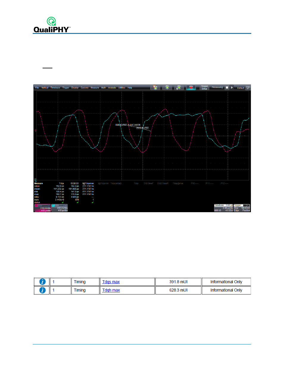
Figure 61 - Oscilloscope Configuration after the Tdqs test
Shown on this screen:
• Z2 is a zoom of F2, the acquired DQS signal after any probe deskew has been applied. The zoom is
positioned at the location of the “worst case” Tdqs measurement indicated by t@Tdqsmax. A
trace label is applied at Vref on this trace according to the signal name assigned to DQS.
• Z3 is a zoom of F3, the acquired DQ signal after any probe deskew has been applied. The zoom is
positioned at the location of the “worst case” Tdqs measurement indicated by t@Tdqsmax. A
trace label is applied at Vref + (0.5 * VdIVW) on this trace according to the signal name assigned
to DQ.
Figure 62 – Tdqs/Tdqh Results
68
924291 Rev A