Initial signal checking, Figure 11 – verification of ck signal – Teledyne LeCroy QPHY-DDR4 User Manual
Page 21
QPHY-DDR4 Software Option
Initial Signal Checking
Before running QPHY-DDR4 the user should have a quick look at their signals to verify that they make
sense. This section covers some of the basic things which should be verified by the operator before
running QPHY-DDR4.
Expected Channels
By default QPHY-DDR4 expects to see the clock (CK) on CH1, DQS on CH2 and DQ on CH3. This is
what is shown in the connection diagram. The Channel Index variable can always be used to modify any
of these channels.
Signal Amplitude
For best results it is recommended that the signals take up 80% of the grid. In order to adjust the
amplitude of each signal use the Channel Gain variable. The user can determine what the optimal gain
settings are before running QPHY-DDR4 to ensure the best results.
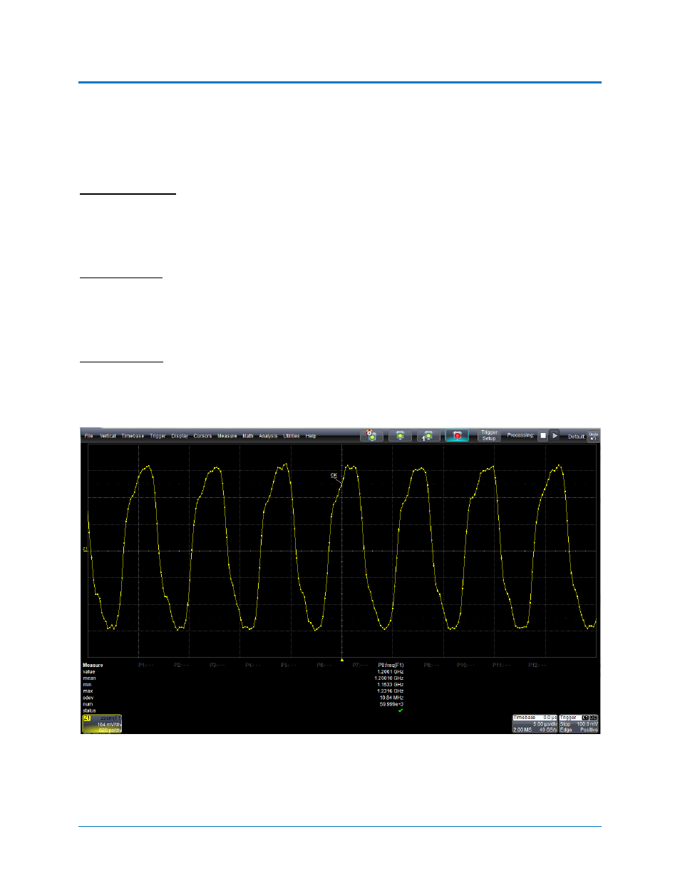
Clock Frequency
By using the frequency parameter on the oscilloscope the user can verify that the DDR system is running
at the transfer rate which the user expects (Transfer Rate =Frequency * 2). This will also help in the limit
selection. The user should also do a quick visual inspection to ensure that the signal does not have any
non-monotonic edges due to reflections.
Figure 11 – Verification of CK signal
924291 Rev A
21