Hardware installation – Teledyne LeCroy PCIe Gen3 M.2 Interposer Quick Start User Manual
Page 6
Hardware Installation
To use this interposer:
1. Set the SW1 DIP switches to the desired clock selection.
Note: "HOST_CLK" should be the default setting unless you are using an external clock reference source.
2. Move the stand off from the default position to the position required by the DUT.
3. Install the M.2 SSD device under test (DUT) into the connector on the interposer as shown (will fit 42mm, 60mm, 80mm
and 110mm).
4. Connect the Summit T3-8 Analyzer (or other compatible Teledyne LeCroy analyzer) to the interposer using the system
iPass cable.
5. Connect the analyzer to a host machine using the USB port on the front panel of the Summit analyzer.
6. If not already done, install the PETracer software on the host machine.
7. Connect 12V DC using the AC adapter supplied with the interposer. (Make sure that the AC adapter is powered on).
8. Power on the analyzer.
9. Power on the host machine.
10. Launch the Teledyne LeCroy software application to monitor, record and view PCI Express traffic passing through the
M.2 Interposer.
11. Power on the system under test.
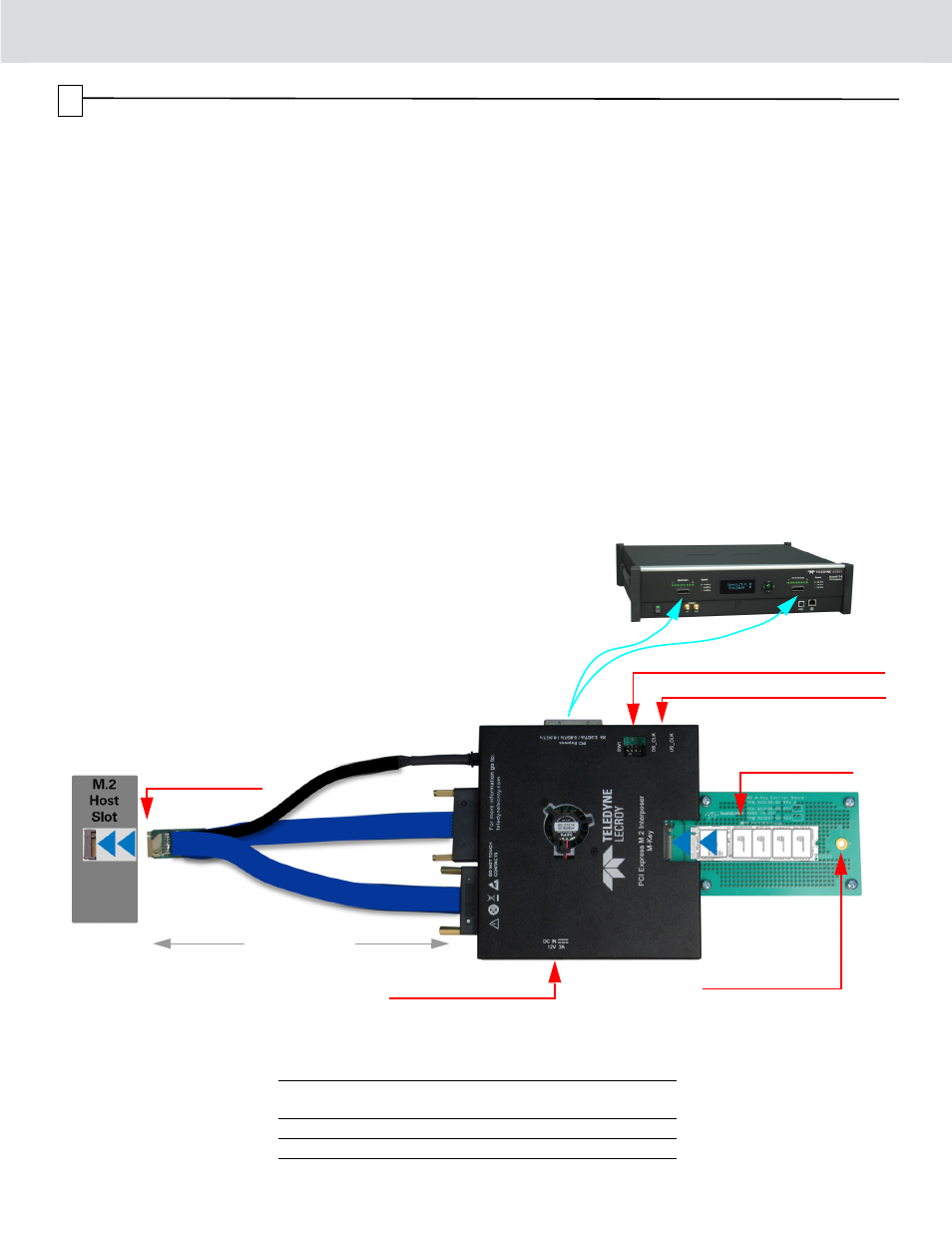
Summit T3-8
Analyzer
M.2 Interposer Interconnection Overview
iPass Y-Cable
PE010UCA-X or
Straight iPass Cable
PE013UCA-X for
Summit T24
External Clock Inputs
Device Under Test
(DUT)
Carrier board
compatible with
22x42, 22x60,
22x80 & 22x110
12V DC from Adapter
475mm (18.7")
(not to scale)
Note: M/B-M Type Interposer is shown
below. The B/M-B Type is physically
similar with a different keying in the slot
for carrier board and host slot connector.
Part No
Connector
Key
Slot Key
B
M
B-M
PE089UIA-X
M-Key
M-Key
No
Yes
Yes
PE090UIA-X
B-Key
B-Key
Yes
No
Yes
Interposer Configurations
Designed For
Host Slot
Connector
Clock Source Configuration SW1
5