Recording traffic, Differential flex tip – Teledyne LeCroy PCI Express 3.0 Multi-Lead Probe PCIe User Manual
Page 4
Recording Traffic
After you have set up the hardware and software, you can record traffic.
For instructions on setting up and implementing a recording, please refer to the PETracer/Trainer User Manual.
5
x16 Configuration
The x16 configuration uses 4 PODs and 4 x4 to x8 iPass Straight Analyzer cables (PE013UCA-X).
•
Connect the Upstream channels 0-7 to one POD according to the Lane Mapping of the Straight Analyzer cable
(0-7).
•
Use the Straight Analyzer cable to connect the POD to Upstream 0-7 ports on the analyzer.
•
Connect the Upstream channels 8-15 to another POD according to Lane Mapping of the Straight Analyzer cable
(0-7). Upstream Lane 8 should be connected to lane 0 on the POD, and Upstream lane 15 should be connected
to lane 7 on the POD.
•
Use the Straight Analyzer cable to connect the POD to Upstream 8-15 ports on the analyzer.
•
Do the same for Downstream channels using the other PODs.
Differential Flex Tip
Attaching the Tip to the Probing Point
1.
The Flex Tip is pre-installed with 0.1 inch long leads.
a. It is recommended to trim the length of the tip as short as possible to improve signal fidelity margin at the analyzer.
The two leads must be cut to the length of +/- 0.01 inches.
2.
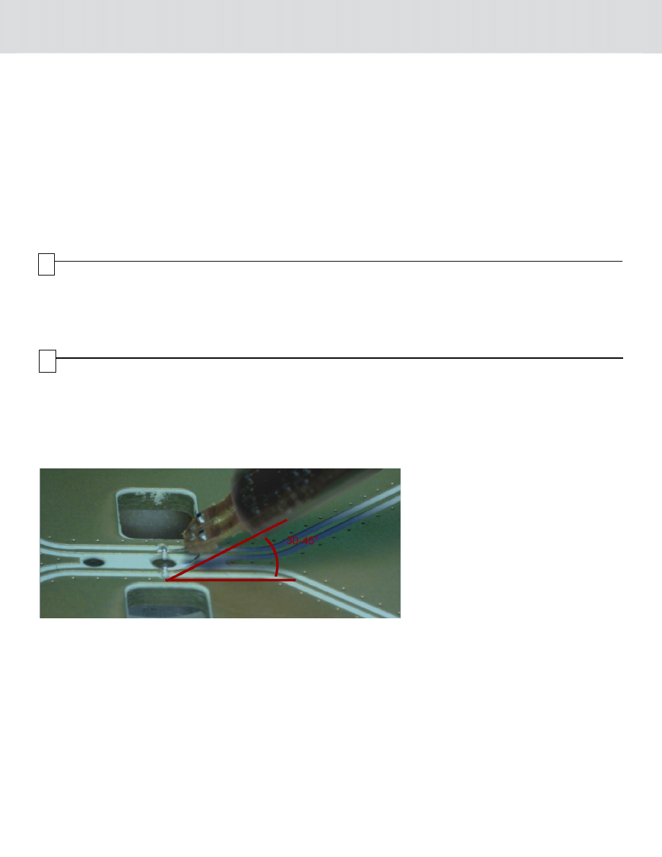
Once soldered, the tip head must be angled at 30-45 degrees to the plane of printed circuit board. Refer to the following figure.
a. Avoid placing the tip directly over any components.
b. A tip holder, supplied with the probe, can be used to secure the tip assembly at the desired angle.
Tip Wire Replacement
Perform the following procedure to replace the tip wire:
1.
Heat the wire at the via with the soldering iron. Carefully remove the existing wire segment from the via.
2.
Free the via barrel of excess solder.
3.
Cut approximately two to three inch wire segment from the wire spool (supplied).
4.
Thread the wire segment through the via located at the tip.
5.
Apply small amounts of solder on the under-side of the tip at the via and heat with a soldering iron until the wire is retained in the
via.
6.
Trim the wire on the top of the flex tip as short as possible to the surface of the printed circuit board.
7.
Trim the probe wire to a maximum length of 0.1,
0.01
inches.
6