Hardware installation – Teledyne LeCroy PCI Express 3.0 Multi-Lead Probe PCIe User Manual
Page 2
3
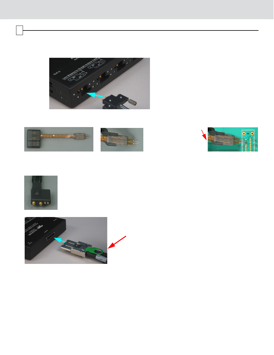
Hardware Installation
To install the components:
1. Plug the High Bandwidth Coax Cable Assembly into the Gen3 Multi-lead POD, as shown below.
2. Solder the Differential Flex Tip at the PCIe Bus sampling point on the DUT.
The Differential Flex tip can withstand several solder/de-solder cycles.
3. You can use a retention unit (plastic guide) for each of the Differential Flex Tips and secure it on the DUT to relieve
stress at the solder joint between the flex tip and the PCIe Bus sampling point.
4. Plug Differential Probe Tip, for an A pair or a B pair, into one Differential Flex Tip.
The Gen3 Multi-lead POD identifies the A and B configurations on the label.
5. Connect the Gen3 Multi-lead POD to a Summit T3 Analyzer using the analyzer cable.
6. Configure the clock. The Gen3 Multi-lead POD supports Internal or External clock configuration.
Internal Clock Configuration: You do not need to use the clock cables. The Summit T3 Analyzer uses its internal
clock source to time PCIe signals.
External Clock Configuration (optional): You need to use the clock cables (PE014UCA-X) (see photo in Compo-
nents). The POD has two connectors for External clock configuration: Clock In and Clock Out.
For Half-width (x4) configuration, which uses one POD, connect a clock cable (PE014UCA-X) to the Clock In connec-
tor on the POD. Connect the other end of the clock cable to the PCIe clock source on the DUT platform.
Plug this end into the
Gen3 Multi-lead POD
Solder this end
to the PCIe bus
Sampling Point
Plug the Differential Probe
Tip into the Flex tip on
this side
Y cable (PE010UCA-X) for
Summit T3 Analyzer