Cable configuration – Teledyne LeCroy PCI Express 3.0 Multi-Lead Probe PCIe User Manual
Page 3
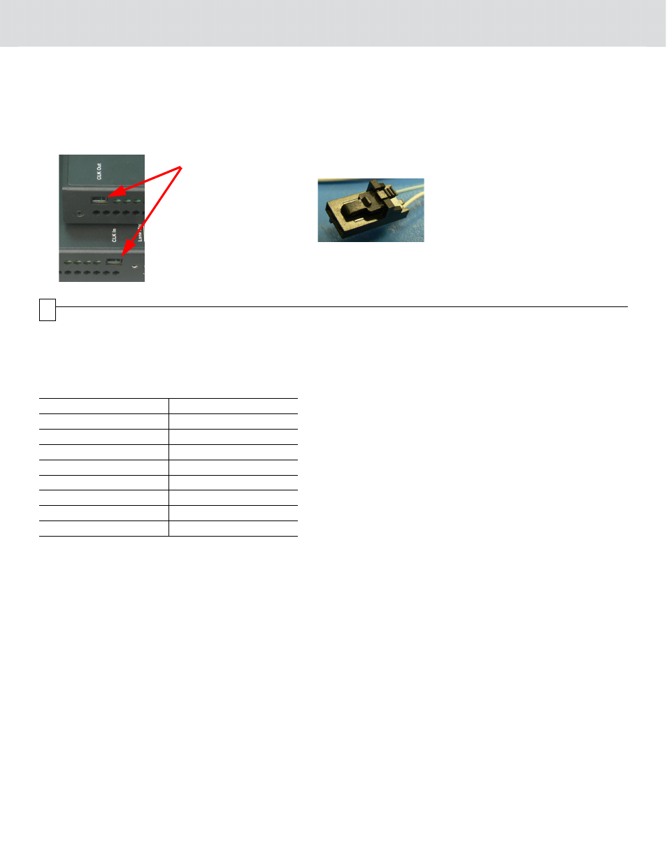
For x8 and x16 configurations, which use multiple PODs, connect a (PE009UCA-X) Daisy chain clock cable to the
Clock In connector on one POD. Connect the other end of the clock cable to the PCIe clock source on the DUT plat-
form.
Connect the second clock cable to the Clock Out connector on that POD. Connect the other end of the second clock
cable to the Clock In connector of the other POD. Similarly, connect additional PODs.
This configuration cascades Gen3 Multi-lead PODs using the same clock source from the DUT platform.
Clock
Connectors
on the POD
Connect a Clocking Cable
Assembly connector to
"Clock In" or "Clock Out"
on the POD.
4
Cable Configuration
x1-x4 Configuration
The x1 -x4 configuration uses 1 POD and the Y analyzer cable.
Connect the Probe tips to the POD according to the following table:
•
Connect the A side of the Y cable to Upstream connector on the analyzer.
•
Connect the B side of the Y cable to Downstream connector on the analyzer.
x8 Configuration
The x8 configuration uses 2 PODs and 2 Straight Analyzer cables.
•
Connect the Upstream lanes to one POD according to the Lane Mapping of the Straight Analyzer Cable (0-7).
•
Use the Straight Analyzer cable to connect the POD to the Upstream port on the analyzer.
•
Do the same for Downstream channels using the second POD.
Probe Lane
POD Connection
Upstream lane 0
A0
Upstream lane 1
A1
Upstream lane 2
A2
Upstream lane 3
A3
Downstream lane 0
B0
Downstream lane 1
B1
Downstream lane 2
B2
Downstream lane 3
B3