Teledyne LeCroy PCI Express 3.0 Multi-Lead Probe PCIe User Manual
Gen3 multi-lead probe™ user manual
Gen3 Multi-lead Probe™
User Manual
Before Starting
Use this document for quick installation and setup. If you
experience problems or need more information, see the
PETracer/Trainer User Manual on the Installation CD or at the
Teledyne LeCroy web site. For details about the latest software
version, see the PCIeProtocolSuite_ReadMe file on the
Installation CD.
Introduction
The Teledyne LeCroy Gen3 Multi-lead Probe™ is designed to tap
and test inter-chip signaling on a PCI Express board. Figure 1
shows the complete assembly of the Gen3 Multi-lead Probe and its
components.
A Gen3 Multi-lead Probe has a Gen3 Multi-lead POD (POD in
Figure 1), High Bandwidth coax cables (C), and a
Differential Flex Tip Assembly for easy connection (for photo, see
Section 2, Components).
Figure 1 also shows a Y cable (Y), which connects to a Summit T3
Analyzer. The External Clock Cable (E) is optional.
One Multi-lead POD is required for link widths of up to x4. x8 link
width requires two PODs. x16 link width requires four PODs.
Figure 1 shows an x2 connection. See Section 4, Cable
Configuration for analyzer cable configurations and lane mapping.
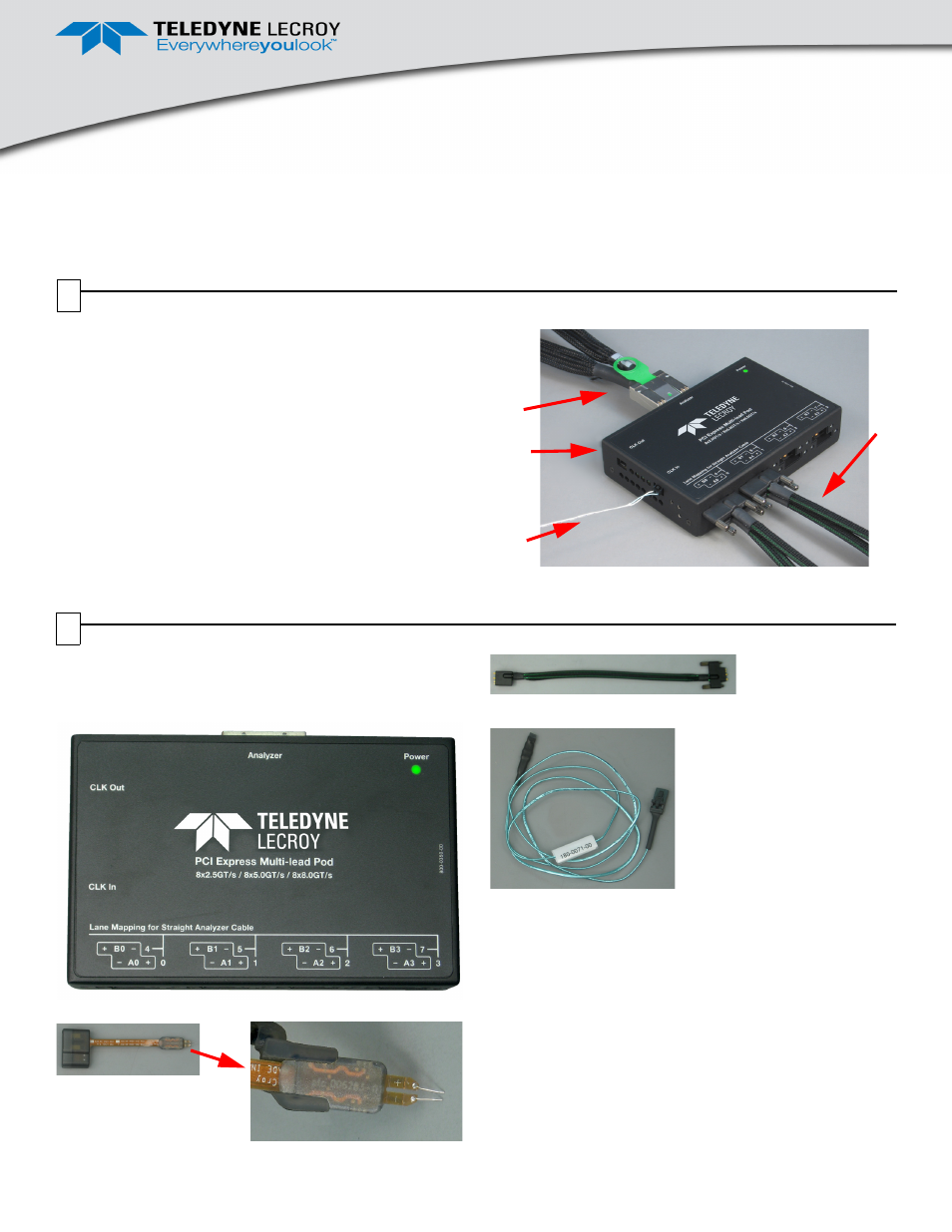
Figure 1. Teledyne LeCroy Gen3 Multi-lead Probe and
Components
C
POD
Y
E
Components
The Teledyne LeCroy Gen3 Multi-lead Probe has the
following components:
•
Gen3 Multi-lead POD (POD in Figure 1)
•
Gen3 Multi-lead Probe Differential Flex Tip
•
High Bandwidth Coax Cable Assembly (C in Figure 1)
•
Clocking Cable Assembly
•
Retention Modules, which are plastic guides for
connecting cables at the DUT (not shown here; see
description in Section 3, Hardware Installation)
Note: To connect to a Summit T3 Analyzer, you need
one iPass Y cable (PE010UCA-X) for
configurations up to x4, two iPass Y cables and
two pods for x8 configurations, and four x4 to x8
straight iPass cables (PE013UCA-X) and four
pods for x16 configurations.
1
2