Teledyne LeCroy PCI Express 2.0 Multi-Lead Probe User Manual
Page 3
For Full-width (x8) configuration, which uses two PODs, connect a reference clock cable to the Clock In connector on
one POD. Connect the other end of the clock cable to the PCIe clock source on the DUT platform. Connect a daisy
chain clock cable to the Clock Out connector on that POD. Connect the other end of the second clock cable to the
Clock In connector of the second POD. This configuration cascades two Gen2 Multi Lead PODs using the same clock
source from the DUT platform. For a x16 configuration four probe pods are required. Connect one reference clock
cable from the DUT to the first pod, and then use three daisy chain cables to connect each pod in sequence.
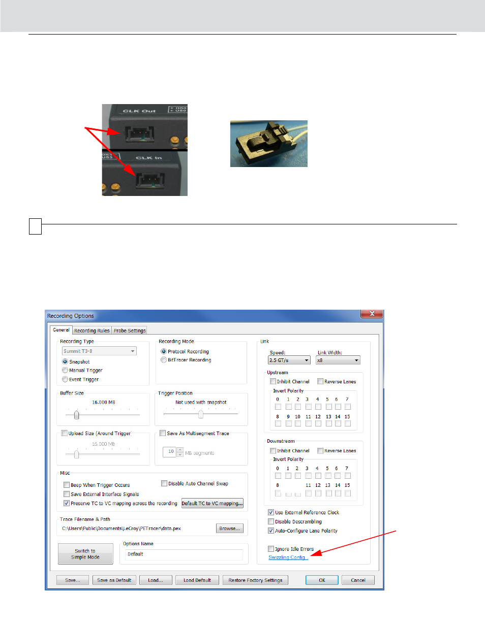
7. Connect the power supply to the pod.
Clock
Connectors
on the POD
Connect a Daisy Chain Cable
Assembly connector to "Clock In"
or "Clock Out" on the POD when
using multiple pods.
4
Software Configuration
After the Summit Analyzer and Multi-Lead Probe are properly setup, use the PETracer software to record traffic in the link.
The default configuration of the Gen2 Multi-Lead Probe Assembly is the (x4 width) configuration.
You must first create the correct swizzling (lane mapping) setup in the Recording Options dialog.
To setup the swizzling configuration:
1. Open the PETracer application on the host machine.
2. Open the Recording Options dialog.
3. In the Recording Type section (top left) your connected analyzer must be displayed.