Teledyne LeCroy PCI Express 2.0 Multi-Lead Probe User Manual
Teledyne LeCroy Equipment
Introduction
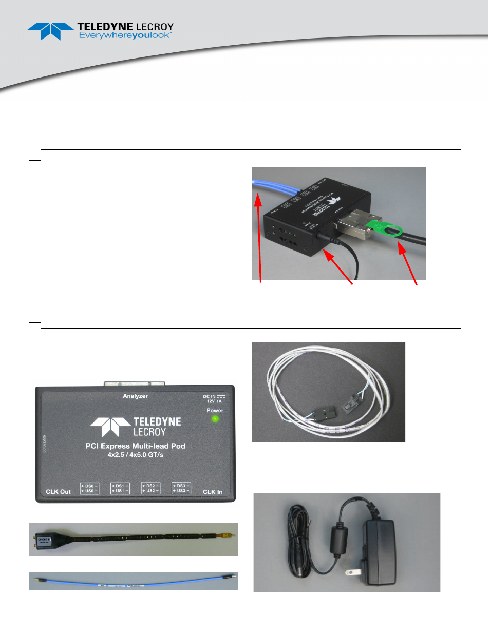
The Teledyne LeCroy Gen2 Multi-Lead Probe (Figure 1) is
designed to tap and test inter-chip signaling on a PCI Express
board.
A Gen2 Multi-Lead Probe has a Gen2 Multi-Lead POD (POD in
Figure 1), High Bandwidth coax cables (C), and a
Differential Flex Tip Assembly for easy connection (for photo, see
Section 2, Components).
Figure 1 also shows an iPass x4 to x8 straight cable (S), which
connects to a Summit T24™ Analyzer. The Summit T3-16, T3-8
and T28 use a Y cable and do not require an external power
supply.
Teledyne LeCroy makes two versions of the Gen2 Multi Lead
Probe. The Half-width probe is up to x4 lane width. The Full-width
probe up to is x8 lane width.
Figure 1. Teledyne LeCroy Gen2 Multi-Lead Probe Pod and
Components (Ref clock cable not shown)
C
S
POD
Gen2 Multi-Lead Probe
User Manual for Summit™
Analyzers
Before Starting
Use this document for quick installation and setup. If you
experience problems or need more information, see the
product manuals available at the Teledyne LeCroy web site or
in the Documents folder in the PETracer installation CD.
Components
The Teledyne LeCroy Gen2 Multi-Lead Probe has the
following components:
•
Gen2 Multi-Lead POD (POD in Figure 1)
•
Gen2 Multi-Lead Probe Differential Flex Tip
•
High Bandwidth Coax Cable Assembly (C in Figure 1)
•
Clocking Cable Assembly
•
Retention Modules, which are plastic guides for
connecting cables at the DUT (not shown here; see
description in Section 3, Hardware Installation).
•
Power Supply shown below (only required for T24):
1
2