Hardware installation – Teledyne LeCroy PCI Express 2.0 Multi-Lead Probe User Manual
Page 2
3
Hardware Installation
To install the components:
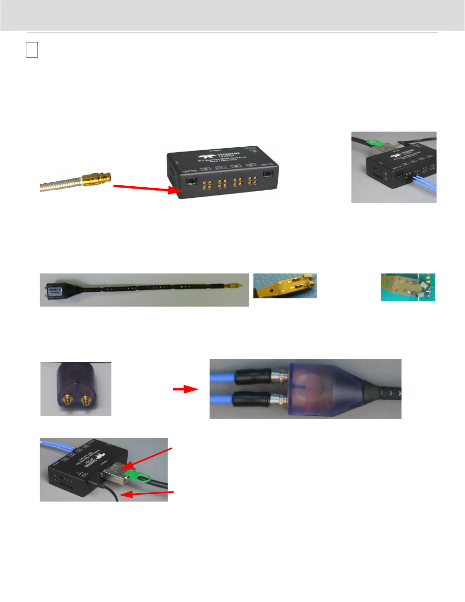
1. Plug the coax cables into the Gen2 Multi-Lead POD, as shown below.
The probe assembly needs one coax cable for each of the Positive (P) and Negative (N) signals.
Important! Be sure to plug the coax cable SSMP connector (gold color) into the POD. Do not attempt to plug the
other end (for the Differential Flex Tip - silver color) into the POD. Attempting to plug the silver end into the POD
will damage the SSMP connector on the Gen2 Multi-Lead POD.
2. Solder the Differential Flex Tip at the PCIe Bus sampling point on the DUT.
The Differential Flex tip can withstand several solder/de-solder cycles.
One Differential Flex tip samples one Upstream or one Downstream differential signal. Therefore, the number of flex
tips needed depends on the number of Downstream or Upstream differential signals to sample. Each Flex Tip is sup-
plied with two 470 ohm resistors. If a specific device under test requires a different resistor value to optimize system
performance other sizes are available, please refer to the datasheet on the Teledyne LeCroy website.
Each set of two resistors will retrofit one Flex Tip assembly. Use standard RF soldering techniques
3. Attach a retention unit (plastic guide) for each of the Differential Flex Tips and secure it on the DUT to relieve stress at
the solder joint between the flex tip and the PCIe Bus sampling point.
4. Plug two coax cables, for an Upstream pair or a Downstream pair, into one Differential Flex Tip.
The Gen2 Multi-Lead POD identifies the Upstream and Downstream configurations on the label.
5. Connect the Gen2 Multi-Lead POD to a Summit T24 Analyzer using the
iPass x4 to x8
straight cable supplied with the
analyzer. Use the iPass Y cable with other Summit Analyzers.
6. Configure the clock. The Gen2 Multi-Lead POD supports Internal or External clock configuration.
Internal Clock Configuration: You do not need to use the clock cable. The Summit Analyzers use their internal clock
source to time PCIe signals.
External Clock Configuration: You need to use the clock cable supplied with the POD (see photo in Components).
The POD has two connectors for External clock configuration: Clock In and Clock Out.
For a x4 configuration, connect a clock cable to the Clock In connector on the POD. Connect the other end of the clock
cable to the PCIe clock source on the DUT platform.
Plug this end into the
Gen2 Multi-Lead POD.
4 Coax Cables in
the POD.
(lane width x1
bi-directional)
Solder this end
to the PCIe
Sampling Point.
Plug the coax
cables
into the Flex tip
on this side
iPass x4 to x8 Straight cable (T24 only)
iPass Y cable for T3-16, T3-8 and T28
Power only for T24