Teledyne LeCroy HFP2500 User Manual
Page 40
HFP2500 High Frequency Probe
34
922253-00 Rev
A
Adjust Offset Range
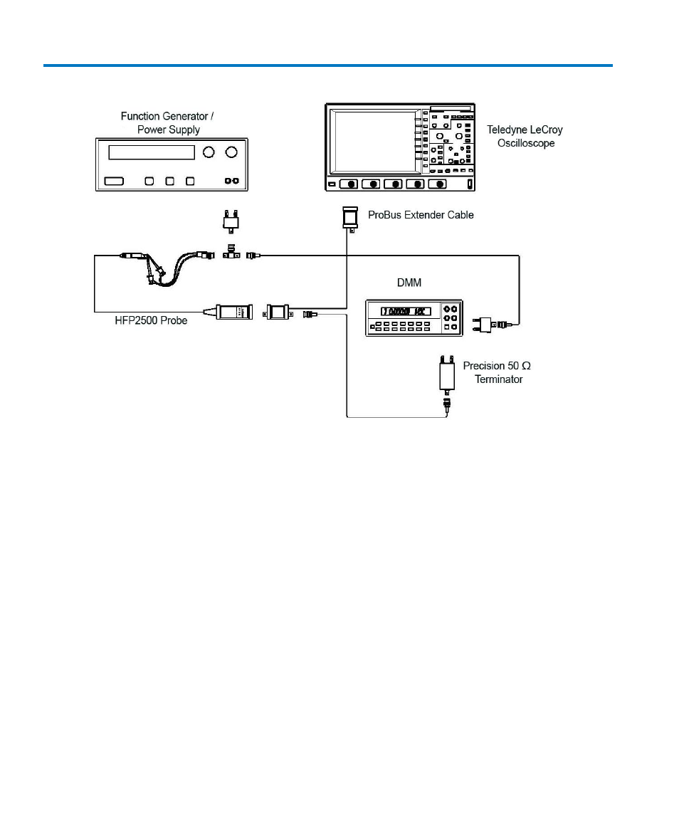
Figure 10, Offset Range Adjustment Setup
1. Connect the BNC end of the BNC to mini-grabber cable to a female end of the BNC tee
adapter and a female BNC to dual banana plug adapter to the male end of the BNC tee.
2. Carefully insert Straight Tips (supplied in the accessory kit) into the HFP2500 probe head
sockets. Attach the red lead of the mini-grabber to the signal input and the black lead to the
ground input of the probe.
3. Set the power supply for approximately 0 Volt.
4. Plug the dual banana plug adapter, with the probe attached, into the output terminal of the
power supply. Make sure the side of the banana plug corresponding to the probe ground
and BNC ground is connected to the negative terminal of the power supply.
5. Attach a BNC cable to the unused female port of the BNC tee and a dual banana plug
adapter to the other end of the BNC cable and plug this into the DMM. Make sure the side
of the banana plug corresponding to the BNC shield (marked ’GROUND’) is connected to the
LO or COMMON input of the DMM. Refer to Figure 10, Offset Range Adjustment Setup for
setup information.